Do you have a question about the Panasonic SA-AK250 and is the answer not in the manual?
| Speakers | 2 |
|---|---|
| CD Player | Yes |
| Number of Discs | 5 |
| Playable Media | CD, CD-R/RW |
| Radio Tuner | Yes |
| Tuner | FM/AM |
| Bluetooth | No |
| USB Playback | No |
| Inputs | AUX |
| Outputs | Headphone |
| Speaker Type | 2-Way |
| Tape Deck | Yes |
Technical specifications for audio output.
Details on radio tuner and connection terminals.
Technical specifications for the cassette tape mechanism.
Details on CD playback capabilities.
General advice for safe operation and maintenance.
Procedures for electrical safety checks.
Precautions before starting repairs.
Information on the unit's protection circuits.
Details on critical safety components.
Techniques to prevent damage to sensitive electronic components.
Guidelines for safely handling the optical pickup traverse unit.
Warnings and precautions regarding laser radiation.
Guidelines for working with lead-free solder.
Part numbers for lead-free solder types.
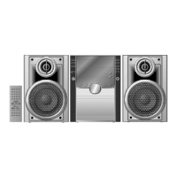
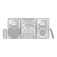
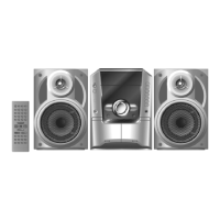
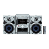
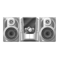
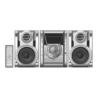
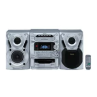
List of items included with the main unit.
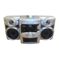
Explanation of buttons and functions on the main unit.
Guide to using the remote control unit.
Instructions for connecting and using external audio devices.
Overview of available diagnostic and test modes.
Details on specific service modes and their operations.
Table listing error codes for the deck mechanism.
Table listing error codes for the CD changer.
Table listing error codes for the power supply.
Procedure to display and clear CRS1 error codes.
Safety notes and visual guide for disassembly.
Instructions for removing the top cabinet and rear panel.
Instructions for removing the main and power supply PCBs.
Steps for disassembling CD changer, deck, and traverse units.
Disassembly of deck mechanism parts and tape jam rectification.
Procedures for replacing pinch rollers, motors, and belts.
List of specialized tools and fixtures for servicing.
Procedure for checking and repairing the main PCB.
Procedure for checking and repairing the transformer PCB.
Procedure for checking and repairing multiple PCBs.
Procedure for checking and repairing the power PCB.
Procedure for checking deck operation with a cassette.
Procedure for checking deck operation without a cassette.
Tools and materials needed for cassette deck measurements.
Unit settings required for measurement procedures.
Steps to prepare for cassette deck measurements.
Procedure for adjusting the tape playback speed.
Procedure for checking bias voltage in the cassette deck.
Procedure for checking bias frequency in the cassette deck.
Voltage and waveform data for the CD servo PCB.
Voltage and waveform data for deck PCBs.
Voltage and waveform data for the main PCB.
Voltage and waveform data for panel and transformer PCBs.
Voltage and waveform data for the power PCB.
Visual examples of various waveforms.
Diagram showing all electrical connections between components.
Functional block diagram of the CD servo system.
Functional block diagram of the deck mechanism.
Overall functional block diagram of the unit.
Functional block diagram of the panel section.
Functional block diagram of the power supply section.
Functional block diagram of the transformer section.
Explanation of symbols and line types used in schematics.
Schematic diagram for the CD servo circuit.
Schematic diagram for the main unit circuits.
Schematic diagram for the panel circuit.
Schematic diagrams for sub-panel and deck mechanism.
Schematic diagram for the power supply circuit.
Schematic diagram for the deck section.
Schematic diagram for the transformer circuit.
Layout diagrams for CD servo, deck, and deck mechanism PCBs.
Layout diagram for the main printed circuit board.
Layout diagram for the panel printed circuit board.
Layout diagram for the sub panel printed circuit board.
Layout diagram for the power supply printed circuit board.
Layout diagram for the transformer printed circuit board.
Illustrations and part numbers for electronic components.
Pin functions for the CD servo processor IC.
Pin functions for the 4-channel drive IC.
Pin functions for the system microprocessor IC.
Diagram showing the location of cabinet parts.
Diagram showing the location of deck mechanism parts.
Illustration of the product's packaging.
Important notes on part replacement and component types.
Replacement parts for the unit's exterior and internal mechanisms.
Lists of ICs, transistors, diodes, resistors, capacitors, etc.
Replacement parts for connections, inductors, and protection.
Lists for oscillators, displays, holders, jacks, wires, and jumpers.