EasyManua.ls Logo

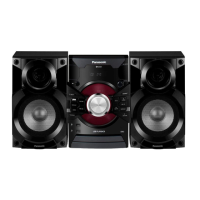
Panasonic SA-AKX17PH User Manual

Panasonic SA-AKX17PH
77 pages
To Next Page IconTo Next Page
Page #1 background imageLoading...
Page #1 background image
© Panasonic Corporation 2013. All rights reserved.
Unauthorized copying and distribution is a violation
of law.
PSG1306001CE
CD Stereo System
Model No. SA-AKX17PH
SA-AKX17PN
Product Color: (K)...Black Type
TABLE OF CONTENTS
PAGE PAGE
1 Safety Precautions----------------------------------------------- 3
1.1. General Guidelines---------------------------------------- 3
1.2. Before Use (For PH only)-------------------------------- 4
1.3. Before Repair and Adjustment ------------------------- 4
1.4. Protection Circuitry ---------------------------------------- 4
1.5. Power Supply using SMPS ----------------------------- 5
1.6. Safety Parts Information --------------------------------- 6
2 Warning-------------------------------------------------------------- 7
2.1. Prevention of Electrostatic Discharge (ESD)
to Electrostatically Sensitive (ES) Devices---------- 7
2.2. Precaution of Laser Diode------------------------------- 8
2.3. Service caution based on Legal restrictions -------- 9
2.4. Handling Precautions for Traverse Unit-------------10
2.5. Grounding for electrostatic breakdown
prevention-------------------------------------------------- 11
3 Service Navigation --------------------------------------------- 12
3.1. Service Information -------------------------------------- 12
4 Specifications ---------------------------------------------------- 13
5 General/Introduction------------------------------------------- 14
5.1. Media Information---------------------------------------- 14
6 Location of Controls and Components------------------ 15
6.1. Remote Control Key Button Operation ------------- 15
6.2. Main Unit Key Button Operation---------------------- 16
7 Installation Instructions -------------------------------------- 17
7.1. Speaker and A/C Connection ------------------------- 17
8 Service Mode ----------------------------------------------------- 18
Please refer to the original service manual for:
CD Mechanism Unit (BRS11C), Order No. PSG1102001CE
Speaker system SB-AKX16PN-K, Order No. PSG1301013CE

Table of Contents

Question and Answer IconNeed help?

Do you have a question about the Panasonic SA-AKX17PH and is the answer not in the manual?

Panasonic SA-AKX17PH Specifications

General IconGeneral
BrandPanasonic
ModelSA-AKX17PH
CategoryStereo System
LanguageEnglish

Summary

Safety Precautions

General Guidelines

General safety advice for servicing and handling the equipment.

Leakage Current Cold Check

Procedure to check for leakage current without power applied.

Leakage Current Hot Check

Procedure to check for leakage current with power applied.

Warning

Prevention of Electrostatic Discharge (ESD) to Electrostatically Sensitive (ES) Devices

Techniques to prevent damage to sensitive components from static electricity.

Precaution of Laser Diode

Safety precautions related to the laser diode used in the product.

Service caution based on Legal restrictions

Guidance on using lead-free solder (PbF) due to legal and environmental restrictions.

Handling Precautions for Traverse Unit

Specific care needed when handling the traverse unit and optical pickup.

Grounding for electrostatic breakdown prevention

Methods for grounding to prevent electrostatic discharge damage.

Service Navigation

Service Information

Technical information for service personnel to understand and service the model.

Firmware Update Procedure

Step-by-step guide for updating the unit's firmware.

Specifications

General/Introduction

Media Information

Details on compatible media formats and playback capabilities.

Location of Controls and Components

Remote Control Key Button Operation

Explanation of each button's function on the remote control.

Main Unit Key Button Operation

Explanation of each button's function on the main unit.

Installation Instructions

Speaker and A/C Connection

Instructions for connecting speakers and the AC power supply.

Service Mode

Cold-Start

Procedure to perform a cold start or initialize the unit to shipping mode.

Doctor Mode Table

Table detailing various doctor modes for diagnostics and checks.

Reliability Test Mode (CD Mechanism Unit)

Process flow charts for aging tests of the CD mechanism unit.

Self-Diagnostic Mode

Instructions to enter and use the self-diagnostic mode for error checking.

Self-Diagnostic Error Code Table

Table listing error codes and their corresponding diagnoses.

Sales Demonstration Lock Function

Procedures for entering and canceling the sales demonstration lock mode.

Troubleshooting Guide

Disassembly and Assembly Instructions

Screw Types

Details on the different types of screws used in the unit.

Disassembly Flow Chart

A flowchart illustrating the sequence of disassembly steps for unit components.

Main Components and P.C.B. Locations

Diagrams showing the location of major components and PCBs within the unit.

Disassembly of Top Cabinet

Step-by-step instructions for removing the top cabinet.

Disassembly of Front Panel Unit

Step-by-step instructions for removing the front panel unit.

Disassembly of Panel P.C.B. and LCD P.C.B.

Instructions for disassembling the panel and LCD PCBs.

Disassembly of Remote Sensor P.C.B.

Instructions for disassembling the remote sensor PCB.

Disassembly of USB P.C.B.

Instructions for disassembling the USB PCB.

Disassembly of CD Lid

Instructions for disassembling the CD lid.

Disassembly of Rear Panel.

Step-by-step instructions for removing the rear panel.

Disassembly of Main P.C.B.

Instructions for disassembling the main PCB.

Disassembly of SMPS Module and Voltage Selector P.C.B.

Instructions for disassembling the SMPS module and voltage selector PCB.

Disassembly of CD Mechanism Unit

Instructions for disassembling the CD mechanism unit.

Disassembly of CD Interface P.C.B.

Instructions for disassembling the CD interface PCB.

Service Position

Checking of Panel P.C.B. and LCD P.C.B.

Procedures for checking the panel and LCD PCBs.

Checking and Repairing of Main P.C.B. (Side B)

Steps for checking and repairing the main PCB, focusing on Side B.

Checking and Repairing of Main P.C.B. (Side A)

Steps for checking and repairing the main PCB, focusing on Side A.

Simplified Block Diagram

Block Diagram

Servo & System Control

Block diagram illustrating servo and system control signal flow.

Audio

Block diagram detailing the audio signal path within the unit.

Power Supply

Block diagram illustrating the power supply circuitry and its distribution.

Wiring Connection Diagram

Schematic Diagram

Schematic Diagram Notes

Notes and symbols used in the schematic diagrams.

MAIN (CD Servo) Circuit

Schematic diagram of the main PCB's CD servo circuit.

MAIN (Micon) Circuit

Schematic diagram of the main PCB's Micon (microprocessor) circuit.

MAIN (Damp) Circuit

Schematic diagram of the main PCB's Damping (amplifier) circuit.

MAIN (Dap_Dsp) Circuit

Schematic diagram of the main PCB's Digital Audio Processor (DAP) and DSP circuit.

MAIN (Tuner_Aux) Circuit

Schematic diagram of the main PCB's tuner and auxiliary input circuit.

MAIN (Voltage Regulator) Circuit

Schematic diagram of the main PCB's voltage regulator circuit.

Panel, LCD, USB, Remote Sensor & CD Interface Circuit

Schematics for panel, LCD, USB, remote sensor, and CD interface circuits.

Printed Circuit Board

Main P.C.B.

Layout diagram for the main printed circuit board (Side A and Side B).

Panel, LCD, USB & Remote Sensor P.C.B.

Layout diagrams for panel, LCD, USB, and remote sensor PCBs.

CD Interface P.C.B.

Layout diagram for the CD interface printed circuit board.

Appendix Information of Schematic Diagram

Voltage Chart

Table of standard voltage values measured at various points on the main PCB.

Main P.C.B. (1/4)

Voltage chart data for the main PCB, sections 1/4.

Main P.C.B. (2/4)

Voltage chart data for the main PCB, sections 2/4.

Main P.C.B. (3/4)

Voltage chart data for the main PCB, sections 3/4.

Main P.C.B. (4/4)

Voltage chart data for the main PCB, sections 4/4.

LCD P.C.B.

Voltage chart data for the LCD PCB.

Waveform Table

Table showing waveform examples for various ICs during playback.

Exploded View and Replacement Parts List

Exploded View and Mechanical Replacement Part List

Exploded views of unit components and lists of mechanical replacement parts.

Cabinet Parts Location

Diagram showing the location of cabinet parts with reference numbers.

Packaging

Diagram illustrating the packaging of the unit and its accessories.

Mechanical Replacement Part List

Detailed list of mechanical replacement parts with part numbers and descriptions.

Electrical Replacement Parts List

Detailed list of electrical replacement parts with part numbers and descriptions.

Related product manuals