© Panasonic Corporation 2016. All rights reserved.
Unauthorized copying and distribution is a violation
of law.
PSG1601001CE
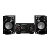
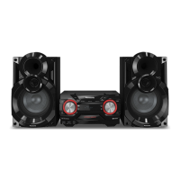
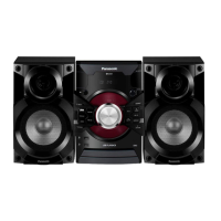
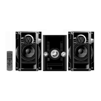
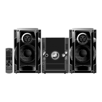
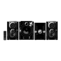
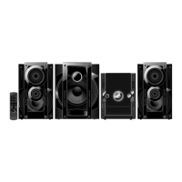
CD Stereo System
Model No. SA-AKX220PN
SA-AKX220PS
SA-AKX440PN
SA-AKX440PS
Product Color: (K)...Black Type
(W)...White Type (For SA-AKX220)
TABLE OF CONTENTS
PAGE PAGE
1 Safety Precautions----------------------------------------------- 3
1.1. General Guidelines---------------------------------------- 3
1.2. Before Repair and Adjustment ------------------------- 4
1.3. Protection Circuitry---------------------------------------- 4
1.4. Power Supply using SMPS Module------------------- 4
1.5. Safety Parts Information --------------------------------- 7
2 Warning-------------------------------------------------------------- 8
2.1. Prevention of Electrostatic Discharge (ESD)
to Electrostatically Sensitive (ES) Devices---------- 8
2.2. Precaution of Laser Diode------------------------------- 8
2.3. General description about Lead Free Solder
(PbF)---------------------------------------------------------- 9
2.4. Handling Precautions for Traverse Unit-------------- 9
2.5. Grounding for electrostatic breakdown
prevention-------------------------------------------------- 10
3 Service Navigation --------------------------------------------- 11
3.1. Service Information-------------------------------------- 11
4 Specifications---------------------------------------------------- 12
5 Location of Controls and Components------------------ 13
5.1. Remote Control Key Button Operation ------------- 13
5.2. Main Unit Key Button Operation---------------------- 14
6 Service Mode----------------------------------------------------- 16
6.1. Cold-Start -------------------------------------------------- 16
6.2. Sales Demonstration Lock Function ---------------- 16
6.3. Doctor Mode Table--------------------------------------- 17
6.4. Self-Diagnostic Mode ----------------------------------- 19
Please refer to the original service manual for:
O CD Mechanism Unit (BRS12C) , Order No. PSG1303059AE
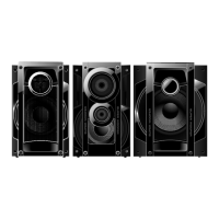
O Speaker system SB-AKX220PN, Order No. PSG1601002CE
O Speaker system SB-AKX440PN, Order No. PSG1601002CE