Do you have a question about the Panasonic SA-CH64M and is the answer not in the manual?
Details amplifier power output, tuner sensitivity, S/N ratio, and cassette deck features.
Covers CD playback parameters, power, dimensions, and weight.
Illustrates the optical pickup, photo detector, and servo amplifier system.
Depicts the circuits for tracking, spindle, and traverse motors.
Provides terminal identification for ICs, transistors, and diodes.
Emphasizes safety precautions for static-sensitive parts and grounding during repair.
Advises on correct fuse types, ratings, and fire hazard prevention.
Details the servo amplifier, optical pickup drive, and motor control circuits.
Covers FM/AM front-end, mixer, and PLL frequency synthesizer circuits.
Explains R/P head interface, pre-amps, bias osc., and output stages.
Describes CD switch control, panel inputs, and operation logic.
Details the jog volume and button input circuitry.
Illustrates control logic, microcomputer interface, and FL display control.
Details the headphone amplifier circuit and associated components.
Explains the BU4052BCF analog switch and BH3854AFS sound processor.
Details core signal path, system control, and buffer amplifier circuits.
Describes LED control, power-down detection, and photo transistor circuits.
Details the main power supply circuitry including transformer and relays.
Illustrates wiring between main PCBs like Servo, Control, and Mechanism.
Shows connections from discrete components to specific printed circuit boards.
Exploded views of tape transport and CD loading mechanism components.
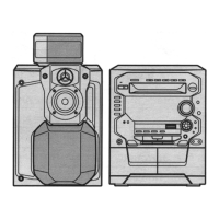
Exploded view of the main chassis, front panel, and external components.
| Brand | Panasonic |
|---|---|
| Model | SA-CH64M |
| Category | Stereo System |
| Language | English |