9.10. Disassembly of Scart P.C.B.
·
Follow Item 9.3.
·
Follow Item 9.9.
Step 1 Detach FFC cable at connector. (CN2008)
Step 2 Remove Scart P.C.B.
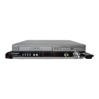
9.11. Disassembly of Main P.C.B.,
AC-Inlet P.C.B. and Tuner
Extent P.C.B.
·
Follow Item 9.7.
·
Follow Item 9.10.
Step 1 Remove 5 screws.
Step 2 Lift up and remove Main P.C.B., AC-Inlet P.C.B. and
Tuner Extent P.C.B.
9.12. Disassembly of Digital Amp IC
(IC5000/IC5200/IC5300)
·
Follow (Step 1) to (Step 2) of Item 9.11.
·
Disassembly of digital amp IC (IC5000).
Step 1 Desolder all the pins of the digital amp IC.
Step 2 Release the claws and remove the heat sink clip.
Step 3 Remove the digital amp IC.
Note: Use same procedures for IC5200 & IC5300 respectively.
9.13. Disassembly of Digital Amp IC
(IC5400)
·
Follow (Step 1) to (Step 2) of Item 9.11.
Step 1 Desolder all pins of IC5400.
Step 2 Desolder 2 pins of Heat Sink B.
Step 3 Remove the Digital Amp IC (IC5400).
Note: Refer to the diagrams of Main P.C.B. (Section 19.2) for
location of the parts.
9.14. Disassembly of Regulator IC
·
Follow (Step 1) to (Step 2) of Item 9.11.
Step 1 Desolder all pins of D5711, D5712, D5716, Q5740.
Step 2 Desolder 2 pins of Regulator IC.
Step 3 Remove the Regulator IC.
35
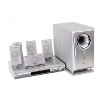
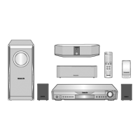
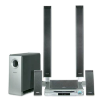
SA-HT540EE
 Loading...