C 230V-240V, 50Hz
Power consumption: 115 W
Dimensions (W×H×D): 430×60×354 mm
Mass: 3.35kg
lAmplifier section
RMS Output Power: Dolby Digital Mode
lTotal RMS Dolby Digital
mode Power:
850 W
At 1kHz and total harmonic of 10%
lFront: 110 W/ Channel (3Ω)
lCenter: 225 W/ Channel (6Ω)
lSurround: 90 W/ Channel (4Ω)
At 100Hz and total harmonic of 10%
lActive subwoofers: 225 W/ Channel (6Ω)
DIN Output Power: Dolby Digital Mode:
lTotal DIN Dolby Digital mode Power:
440 W
At 1kHz and total harmonic of 1%
© 2006 Panasonic AVC Networks Singapore Pte.
Ltd. All rights reserved. Unauthorized copying and
distribution is a violation of law.
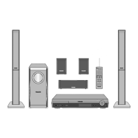
SA-HT855E
SA-HT855EB
SA-HT855EG
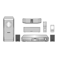
Colour
(S).......................Silver Type
lFront: 80 W/ Channel (3Ω)
lCenter: 75 W/ Channel (6Ω)
lSurround: 65 W/ Channel (4Ω)
At 100Hz and total harmonic of 1%
lSubwoofer: 75 W/ Channel (6Ω)
lFM tuner section
Preset Memory: FM 15 stations
AM/MW 15 stations
Frequency Range: 87.50-108.00MHz
(50kHz in step)
Sensitivity: 1.8µV (IHF)
S/N 26dB
1.4µV
Antenna Terminals: 75Ω (unbalanced)
lAM tuner section
Frequency Range: 522-1629kHz (9kHz in step)
AM Sensitivity S/N 20dB at
999kHz:
560µV/m
lDigital audio input:
Optical digital input: Optical terminal (1 system)
Sampling frequency: 32kHz, 44.1kHz, 48kHz
lPhone Jack:
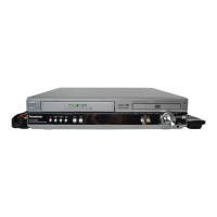
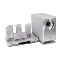
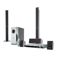
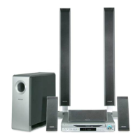
DVD Home Theater Sound System
Specifications
ORDER NO.MD0603062C2