Do you have a question about the Panasonic SA-NS55 and is the answer not in the manual?
Safety advice, cold/hot leakage current testing procedures, and general servicing guidelines.
Crucial steps before starting any repair or adjustment work, including capacitor discharge.
Explains the unit's protection features and troubleshooting steps for activation.
Lists critical safety components that require manufacturer-specified replacement parts.
Lists error codes, diagnosis, FL display, and remarks for troubleshooting.
Standard voltage values for various PCBs, including CD Servo, Main, Panel, Power, Transformer, Motor, and USB.
Visual representations of key signal waveforms at specific test points for diagnosis.
Electronic schematics for CD servo and main processing circuits.
Schematics for Panel, Tuner, Audio, D-Port, USB, Motor, Switch, Transformer, and AC Inlet circuits.
Electronic schematics for the unit's power supply and management circuits.
Detailed pin descriptions and functions for the IC7001 servo processor.
| Brand | Panasonic |
|---|---|
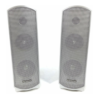
| Model | SA-NS55 |
| Category | Speaker System |
| Language | English |