EasyManua.ls Logo

Panasonic SA-BT230P

Panasonic SA-BT230P
146 pages
To Next Page IconTo Next Page
Loading...
© Panasonic Corporation 2010. All rights reserved.
Unauthorized copying and distribution is a violation
of law.
PSG1001003CE
A6
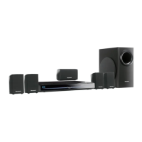
Blu-ray Disc Home Theater Sound System
Model No. SA-BT230P
SA-BT230PC
SA-BT330P
SA-BT330PC
Volume 1
Product Color: (K)...Black Type
Notes: 1) These model’s BD Drive/Main P.C.B. Assembly are:-
- RFKNBT230P (For P);
- RFKNBT230PC (For PC);
- RFKNBT330P (For P);
- RFKNBT330PC (For PC).
2) Please refer to the original service manual for:
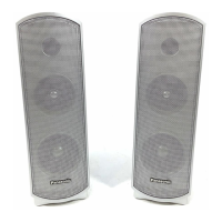
• Speaker system SB-BT230P-K (For SA-BT230P/PC-K), Order No: PSG1001007CE.
• Speaker system SB-BT330P-K (For SA-BT330P/PC-K), Order No: PSG1001008CE.
Caution:
Pairing of BD Drive and Main P.C.B. as “BD Drive & Main P.C.B. Assembly” have to be replaced together. If
either BD Drive or Main P.C.B. is changed, BD Drive unit has to carry out re-adjustment due to alignment
data for BD Drive Unit is stored in the Main P.C.B.

Table of Contents

Questions and Answers:

Panasonic SA-BT230P Specifications

General IconGeneral
BrandPanasonic
ModelSA-BT230P
CategorySpeaker System
LanguageEnglish

Summary

Safety Precautions and Warnings

General Guidelines and Leakage Current Checks

Covers general safety during servicing, leakage current tests, and handling of power cords.

Before Repair and Adjustment Procedures

Guidelines for safely discharging capacitors and applying power after repairs.

Protection Circuitry

Explains the function of protection circuitry and steps to take if it activates.

Safety Parts Information

Lists critical safety components and emphasizes using manufacturer-specified parts.

Warnings and Handling Precautions

Electrostatic Discharge (ESD) Prevention

Techniques to reduce component damage from static electricity when handling ES devices.

Laser Diode Precautions

Safety measures related to the laser diode, including avoiding disassembly and direct exposure.

Legal Restrictions and Lead-Free Solder

Information on lead-free solder usage and handling for environmental conservation.

BD Drive Handling Precautions

Special care instructions for handling the BD drive to prevent static breakdown.

Service Navigation

Service Information

Overview of the service manual's content and ordering parts.

Caution for Replacing Parts

Advises on firmware updates and part replacement procedures.

Standard Inspection Specifications

Checklist for verifying normal operation after repairs.

Specifications

Controls and Components

Remote Control Operations

Detailed explanation of remote control buttons and their functions.

Main Unit Operations

Description of buttons and indicators on the main unit.

BD-LIVE BONUSVIEW Usage

Instructions for using BD-LIVE and BONUSVIEW features in BD-Video discs.

iPodiPhone Integration and Playback

Guidance on connecting and playing content from iPod/iPhone devices.

Speaker Connections

Diagram and instructions for connecting speaker systems to the main unit.

Disc Playability

Information on supported disc types (BD, DVD, CD, SD) and their playable contents.

SD Card Information

Details on SD card usage, compatibility, and data management.

File Format Support and Structures

Supported file extensions (MP3, JPEG, AVCHD, MPEG2) and folder structures.

Operating Instructions

Disc Ejection During Abnormality

Procedures for removing a disc when the unit is not responding normally.

Self-Diagnostic and Special Modes

Special Mode Tables

Details on special modes like Initialize, Rating Password, Service Mode, and Aging.

Error Code Tables

Lists error codes, diagnosis contents, descriptions, and display information.

Service Mode Operations

Instructions for entering and using various service modes for diagnostics and settings.

Troubleshooting Guide

Troubleshooting F61 F76 Errors

Guide to diagnose and resolve F61 and F76 error codes related to power supply issues.

P.C.B. Component Locations for Troubleshooting

Illustrations showing locations of key components on SMPS, Power, and Main P.C.B.s.

Service Fixtures and Tools

Service Tools and Equipment

Lists specific tools and cables required for service operations.

Disassembly and Assembly Instructions

Disassembly Flow Chart

Visual representation of the disassembly sequence for major components.

Main Components and P.C.B. Locations

Diagram illustrating the placement of key internal parts and circuit boards.

Top Cabinet Disassembly

Step-by-step instructions for removing the top cabinet assembly.

AC Inlet P.C.B. Disassembly

Procedure for safely removing the AC inlet printed circuit board.

Optical In P.C.B. Disassembly

Steps for removing the optical input printed circuit board.

Wireless Adapter P.C.B. Disassembly

Instructions for detaching the wireless adapter printed circuit board.

Rear Panel Disassembly

Procedure for removing the rear panel assembly.

Front Panel Block Assembly Disassembly

Steps for removing the front panel block assembly.

Panel P.C.B. Disassembly

Instructions for removing the panel printed circuit board.

Power Button P.C.B. Disassembly

Procedure for removing the power button printed circuit board.

Cradle Lid Replacement

Steps for disassembling and assembling the iPod cradle lid.

iPod Cradle Assembly Replacement

Procedure for replacing the iPod cradle assembly.

iPodiPhone P.C.B. Disassembly

Instructions for removing the iPod/iPhone printed circuit board.

DVD Lid Unit Replacement

Steps for replacing the DVD lid unit assembly.

Front Shield Disassembly

Procedure for removing the front shield assembly.

BD Drive Disassembly Procedures

Covers upper base, tray, pulley, slide cam, gears, motor, lens cleaning.

Main P.C.B. Disassembly

Step-by-step instructions for removing the main printed circuit board.

D-Amp P.C.B. Disassembly

Procedure for removing the digital amplifier board.

Digital Amplifier IC Replacement

Instructions for replacing the digital amplifier ICs (IC5100/IC5200).

Power P.C.B. Disassembly

Procedure for removing the power supply printed circuit board.

SMPS P.C.B. Disassembly

Instructions for removing the switch mode power supply printed circuit board.

Switching Regulator IC Replacement

Steps for replacing the switching regulator IC (IC5701).

Rectifier Diode Replacement

Procedure for replacing the rectifier diode (D5702).

Regulator Diode Replacement

Instructions for replacing regulator diodes (D5802, D5803).

Fan Unit Disassembly

Steps for removing the cooling fan unit.

Service Position and Procedures

Main P.C.B. Checking and Repair

Guidance for checking and repairing both sides of the main printed circuit board.

D-Amp P.C.B. Checking and Repair

Procedures for checking and repairing both sides of the D-Amp printed circuit board.

SMPS P.C.B. Checking and Repair

Instructions for checking and repairing the SMPS printed circuit board.

FL P.C.B. Checking and Repair

Steps for checking and repairing the FL display printed circuit board.

Voltage and Waveform Charts

Main P.C.B. Voltage Data

Standard voltage indication values for the main printed circuit board.

Panel P.C.B. Voltage Data

Standard voltage values for the panel printed circuit board.

D-Amp P.C.B. Voltage Data

Standard voltage indication values for the D-Amp printed circuit board.

Power P.C.B. Voltage Data

Standard voltage indication values for the power printed circuit board.

SMPS P.C.B. Voltage Data

Standard voltage indication values for the SMPS printed circuit board.

Waveform Table

Illustrations of waveforms for various test points and ICs.

Component Illustrations

Block Diagrams

Main - System Control Block Diagram

Shows the system control signal flow within the main unit.

Main - Audio Block Diagram

Illustrates the audio signal processing and routing within the main unit.

Digital Audio Block Diagram

Diagram showing the digital audio signal path and processing stages.

Power Supply Block Diagram

Overview of the power supply sections and their interconnections.

Wiring Diagram

Schematic Diagram Notes

Schematic Diagrams

Main (MiconTuner) Circuit Diagram

Detailed schematic for the main unit's microcontroller and tuner circuitry.

Panel Circuit Diagram

Schematic detailing the front panel display and control circuitry.

D-Amp Circuit Diagram

Schematic showing the digital amplifier circuit.

SMPS Circuit Diagram

Schematic illustrating the switch mode power supply circuitry.

Power, Power Button & AC Inlet Circuits

Schematics for the power supply, button, and AC inlet sections.

iPodiPhone, Optical In & Wireless Adapter Circuits

Schematics for audio input and wireless adapter connectivity.

Printed Circuit Board Layouts

Main P.C.B. Layouts

Component layout diagram for the main printed circuit board.

Panel, Power, Power Button & AC Inlet P.C.B. Layouts

Component layout diagrams for panel, power, button, and AC inlet boards.

D-Amp P.C.B. Layout

Component layout diagram for the digital amplifier printed circuit board.

SMPS P.C.B. Layout

Component layout diagram for the SMPS printed circuit board.

iPodiPhone, Optical In & Wireless Adapter P.C.B. Layouts

Component layout diagrams for iPod, optical, and wireless adapter boards.

Terminal Function of ICs

IC6001 FL Driver Terminal Functions

Pinout and function description for the FL display driver IC.

Exploded Views and Parts Lists

Cabinet Parts Location

Exploded view showing cabinet parts and their locations.

Packaging Details

Diagrams illustrating how the unit and accessories are packaged.

Mechanical Replacement Parts

List of mechanical parts with part numbers and descriptions.

Electrical Replacement Parts

List of electrical components with part numbers and descriptions.

Related product manuals