EasyManua.ls Logo

Panasonic SA-VK81DGCS User Manual

Panasonic SA-VK81DGCS
154 pages
To Next Page IconTo Next Page
Page #1 background imageLoading...
Page #1 background image
n AMPLIFIER SECTION
RMS Output Power : Dolby Digital Mode
Front Ch
80 W per channel (6 ), 1 kHz, 10% THD
Surround Ch
35 W per channel (6 ), 1 kHz, 10% THD
Center Ch
85 W per channel (6 ), 1 kHz, 10% THD
Subwoofer
85 W per channel (6 ), 100 Hz, 10% THD
Total RMS Dolby Digital mode power
400 W
PMPO output power 4800 W
n FM/AM TUNER, TERMINALS SECTION
Preset station FM 15 stations
AM/MW 15 stations
Frequency Modulation (FM)
Frequency range 87.50 - 108.00 MHz (50 kHz step)
Sensitivity 2.5µV (IHF)
S/N 26dB 2.2µV
A
ntenna terminals 75 (unbalanced)
A
mplitude Modulation (AM/MW)
Frequency range 522 - 1629 kHz (9 kHz step)
520 - 1630 kHz (10 kHz step)
A
M sensitivity S/N 20 dB at 1000 kHz
560µV/m
A
udio performance (Amplifier)
© 2004 Panasonic AVC Networks Singapore Pte.
Ltd. (RCB Registration Number: 197701580H) All
rights reserved. Unauthorized copying and
distribution is a violation of law.
SA-VK81DGCS
SA-VK81DGCP
Colour
(S)... Silver Type
Input sensitivity/Input impedance
A
ux 250 mV, 20 k
Phone jack
Terminal Stereo, 3.5 mm jack
Mic jack
Sensitivity 0.7 mV, 600
Terminal Mono, 6.3 mm jack (2 system)
n CASSETTE DECK SECTION
Type Auto Reverse
Track system 4 Track, 2 Channel
Head Record/Playback Solid Permalloy Head
Erasure Double Gap Ferrite Head
Motor DC Servo Motor
Recording System AC Bias 100 kHz
Erase System AC Erase 100 kHz
Tape Speed 4.8 cm/s
Overall Frequency Response (+3, -6 dB) at DECK OUT
Normal (TYPE I) 35 Hz - 14 kHz
S/N Ratio 50 dB (A weighted)
Wow and Flutter 0.18 % (WRMS)
Fast Forward and Rewind Time Approx. 120 seconds with
C-60 cassette tape
n DISC SECTION
Disc played [8 cm or 12 cm]
(1) DVD-RAM (DVD-VR compatible, JPEG formatted disc)
(2) DVD-Audio
DVD Stereo System
Specifications
ORDER NO. MD0406163C3

Table of Contents

Question and Answer IconNeed help?

Do you have a question about the Panasonic SA-VK81DGCS and is the answer not in the manual?

Panasonic SA-VK81DGCS Specifications

General IconGeneral
Speaker Configuration5.1 Channel
BluetoothNo
CD PlayerYes
USB PortYes
FM RadioYes
DVD PlayerYes
TunerFM
Dolby DigitalYes
DTSNo
USB PlaybackYes
Playable MediaCD, MP3
InputsAUX
OutputsComposite Video

Summary

1 Before Use

2 Before Repair and Adjustment

3 Protection Circuitry

4 Safety Precautions

4.1 General Guidelines

General guidelines for safe servicing and handling of the equipment.

5 Prevention of Electro Static Discharge (ESD) to Electrostatically Sensitive (ES) Devices

7 Cautions to be taken when handling Optical Pickup

7.1 Handling Optical Pickup

Precautions for safely handling the optical pickup unit.

7.2 Replacing Precautions for Optical Pickup Unit

Guidelines for replacing the optical pickup unit.

7.3 Grounding for Preventing Electrostatic Destruction

Procedures for grounding to prevent electrostatic discharge damage.

8 Precaution of Laser Diode

10 Operation Procedures

Main unit

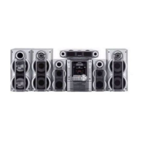
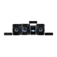
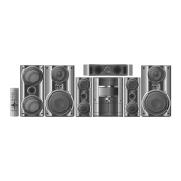
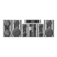
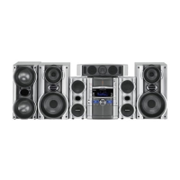
Overview of controls and functions on the main unit.

Center console

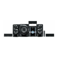
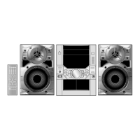
Overview of controls and functions on the center console.

13 Procedure for repairing the set

13.1 Distinguish the problem

Steps to identify the root cause of a problem.

13.1.1 Troubleshooting Guide Part 1

Table of checking points, possible faults, reasons, and countermeasures.

13.1.2 Troubleshooting Guide Part 2

Continuation of troubleshooting guide for various sections.

13.2 Diagnosis of Optical Pick-up Unit

Diagnostic methods to determine the condition of the optical pickup unit.

14 Optical Pickup Self-Diagnosis and Replacement Procedure

14.1 Self-diagnosis

Explanation of the self-diagnosis and tilt adjustment functions.

14.2 Cautions to Be Taken During Replacement of Optical Pickup and Spindle Motor

Precautions for replacing optical pickup and spindle motor.

14.2.1 Cautions to be taken during replacement of optical pickup

Safety measures related to static electricity and handling the optical pickup.

15 Self-Diagnosis Function

15.2 Memorized Error Codes

How to activate and display memorized error codes.

15.4 DVD/CD Self-Diagnosis Error Code Description

15.8 Things to Do After Repair

16 Cautions To Be Taken During Servicing

16.1 Recovery after the dvd player is repaired

Procedure to optimize the drive after replacing Flash ROM or module.

16.4 Using Recovery Disc

Steps for performing recovery and version upgrade with a recovery disc.

16.6 After replacement of DVD Module

17 Disassembly and Assembly of Main Component

17.1 Disassembly flow chart

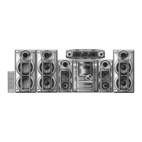
Flowchart illustrating the disassembly procedure for internal inspection.

17.5 Disassembly of Main P.C.B., Power P.C.B., Power Supply P.C.B., Transformer P.C.B. & Voltage Selector P.C.B.

17.6 Replacement for traverse deck

17.7 Replacement for optical pickup unit (DVD mechanism)

17.9 CR16 mechanism disassembly procedure

17.10 CR16 MECHANISM ASSEMBLY PROCEDURE

17.11 Disassembly for Traverse Unit

17.12 Disassembly of Deck Mechanism Unit

17.14 Counter-measure for tape trouble

18 Service Position

18.3 Checking the Panel P.C.B., Tact Switch P.C.B., Mic P.C.B., Deck P.C.B. & Deck Mechanism P.C.B.

19 Measurements and Adjustments

19.1 Cassette Deck Section

Adjustments specific to the cassette deck.

19.1.1 Head Azimuth Adjustment (Deck 1/2)

Detailed steps for adjusting the head azimuth on the cassette deck.

19.1.2 Tape Speed Adjustment (Deck 1/2)

Procedure for adjusting the tape speed on the cassette deck.

19.2 Tuner Section

Adjustments for the tuner.

21 Schematic Diagram

21.1 Optical Pickup Unit Circuit

Schematic diagram of the optical pickup unit circuit.

21.2 (A) DVD Module Circuit

Schematic diagram for the DVD module circuit.

21.3 (B) Main Circuit

Schematic diagram of the main circuit.

21.6 (H) Power Supply Circuit

Schematic diagram of the power supply circuit.

21.7 (I) Power Amp Circuit

Schematic diagram of the power amplifier circuit.

21.8 (J) Power Circuit

Schematic diagram of the power circuit.

25 Terminal Function of IC

25.1 IC6800 (C2CBJG000460) System Microprocessor

Pin functions for the System Microprocessor IC6800.

26 Parts Location and Replacement Parts List

26.4 Electrical Parts List

List of part numbers and names for integrated circuits and transistors.

26.4.1 Electrical Parts List

List of part numbers and names for diodes and chip inductors.

26.4.2 Electrical Parts List

List of part numbers and names for resistors and switches.

26.4.3 Electrical Parts List

List of part numbers and names for resistors and capacitors.

Related product manuals