EasyManua.ls Logo

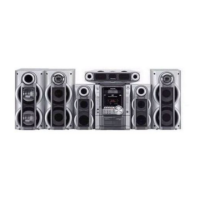
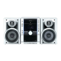
Panasonic SA-VK31GC User Manual

Panasonic SA-VK31GC
116 pages
To Next Page IconTo Next Page
Page #1 background imageLoading...
Page #1 background image
n AMPLIFIER SECTION
PMPO 2500 W
RMS power output
THD 10% both channels driven
1 kHz (Low channel) 75 W per channel (6 )
10kHz (High channel) 75 W per channel (6 )
Total Bi-Amp power 150 W per channel
A
UX
Input sensitivity 250 mV
Input Impedance 13.3 k
Phone jack
Terminal Stereo, 3.5 mm jack
MIC jack
Sensitivity 0.7 mV, 680
Terminal Mono, 3.5 mm jack (2 system)
n FM TUNER SECTION
Frequency range 87.50 - 108.00 MHz (50 kHz steps)
Sensitivity 2.5µV (IHF)
S/N 26 dB 2.2 µV
A
ntenna terminal(s) 75 (unbalanced)
n AM TUNER SECTION
Frequency range 522 - 1629 kHz (9 kHz steps)
520 - 1630 kHz (10 kHz steps)
Sensitivity
© 2004 Panasonic AVC Networks Singapore Pte.
Ltd. (RCB registration number: 197701580H) All
rights reserved. Unauthorized copying and
distribution is a violation of law.
SA-VK31GC
SA-VK31GS
Colour
(S)... Silver Type
S/N 20 dB (at 999 kHz) 560 µV/m
n CASSETTE DECK SECTION
Track system 4 track, 2 channel
Heads
Record/playback Solid permalloy head
Erasure Double gap ferrite head
Motor DC servo motor
Recording system AC bias 100 kHz
Erasing system AC erase 100 kHz
Tape speed 4.8 cm/s
Overall frequency response (+3 dB, -6 dB at DECK OUT)
NORMAL (TYPE I) 35 Hz - 14 kHz
S/N 50 dB (A weighted)
Wow and flutter 0.18 % (WRMS)
Fast forward and rewind time Approx. 120 seconds with
C-60 cassette tape
n CD SECTION
Discs played [8 cm or 12 cm]
(1) CD- Audio (CD-DA)
(2) Video CD
(3) CD-R/RW (CD-DA, MP3 disc)
(4) MP3
Sampling frequency 44.1 kHz
Decoding 16 bit linear
CD Stereo System
Specifications
ORDER NO. MD0405174C3

Table of Contents

Question and Answer IconNeed help?

Do you have a question about the Panasonic SA-VK31GC and is the answer not in the manual?

Panasonic SA-VK31GC Specifications

General IconGeneral
TunerFM/AM
BluetoothNo
USB PlaybackNo
Number of Channels2.1
DVD PlayerYes
Disc PlaybackCD
Playable MediaCD, CD-R/RW

Summary

Safety Precautions (for GS Only)

Before Use (For GC Only)

Before Repair and Adjustment

Protection Circuitry

Prevention of Electro Static Discharge (ESD) to Electrostatically Sensitive (ES) Devices

Handling the Lead Solder

About lead free solder (PbF)

Details on using lead-free solder, including melting points and handling.

Handling Precautions For Traverse Deck

Handling of traverse deck (optical pickup)

Precautions for handling the sensitive traverse deck and optical pickup.

Grounding for electrostatic breakdown prevention

Methods for grounding to prevent damage from static electricity.

Precaution of Laser Diode

Accessories

Operation Procedures

Operation Checks and Main Component Replacement Procedures

11.1. Disassembly of Top Cabinet and Rear Panel

Step-by-step guide for removing the top cabinet and rear panel.

11.2. Disassembly of CD Mechanism Unit

Procedure for taking apart the CD mechanism unit.

11.3. Disassembly Main P.C.B., Transformer P.C.B. & MP3 P.C.B.

Steps to disassemble main, transformer, and MP3 circuit boards.

11.4. Disassembly of Panel P.C.B. & Tact Switch P.C.B.

Guide for removing panel and tact switch circuit boards.

11.5. Disassembly of Deck Mechanism Unit & Deck P.C.B.

Procedure for dismantling the deck mechanism and circuit board.

11.6. CD Mechanism Main Component Replacement Procedures

Steps for replacing main components of the CD mechanism.

11.7. Disassembly Deck Mechanism

Instructions for disassembling the deck mechanism.

11.8. Replacement for the cassette lid ass’y

Procedure for replacing the cassette lid assembly.

11.9. Measure for tape trouble

Steps to diagnose and resolve tape playback issues.

Service Position

12.1. Checking the Main P.C.B., Power P.C.B., Transformer P.C.B. and Voltage Selector P.C.B.

Guide for checking specific circuit boards in the service position.

12.2. Checking the Panel P.C.B., Tact Switch P.C.B., Deck P.C.B. & Deck Mechanism P.C.B.

Instructions for checking panel, tact switch, deck, and mechanism boards.

Description of Error Code

13.1. Abnormality Detection for DECK Mechanism

Lists error codes and problems related to the deck mechanism.

13.2. Abnormality detection for CD/Changer Block

Error codes and problems for the CD/changer block.

13.3. Power Supply Related Error Detection

Error codes and issues related to the power supply.

Self-Diagnostic Function

14.1. Self-diagnostic display

Explains the self-diagnostic display function for error codes.

14.2. How to enter the Self-Diagnostic Function

Step-by-step instructions to access the self-diagnostic mode.

14.3. Cassette Mechanism Test (For error code H01, H02, H03, F01)

Procedure for testing the cassette mechanism for specific error codes.

14.4. CD Mechanism Test (F15, F26, F16, F17, F27, F28, F29, H15)

Test procedure for the CD mechanism with specific error codes.

14.5. To clear all Error code

Method to reset or clear all recorded error codes.

14.6. How to get out from Self-Diagnostic function

Instructions on exiting the self-diagnostic mode.

14.7. Power Amplifier Failure (F61)

Information on identifying power amplifier failure via error code F61.

CD Test Mode Function

15.1. How to set CD test mode

Steps to activate the CD test mode for diagnostics.

15.2. CD Automatically Adjustment result indication

How to interpret automatic adjustment results in CD test mode.

Measurements and Adjustments

16.1. Cassette Deck Section

Procedures for measuring and adjusting the cassette deck section.

16.2. Tuner Section

Procedures for measurements and adjustments specific to the tuner section.

16.3. Alignment Points

Identifies specific points for alignment procedures.

Block Diagram

Related product manuals