EasyManua.ls Logo

Panasonic SA-VK960GC User Manual

Panasonic SA-VK960GC
151 pages
To Next Page IconTo Next Page
Page #1 background imageLoading...
Page #1 background image
Q
QQ
Q AMPLIFIER SECTION
RMS Output Power: Dolby Digital Mode
OFront Ch (High Ch) 110 W per channel (3 ), 1 kHz,
10% THD
OFront Ch (Low Ch) 55 W per channel (6 ), 100 Hz,
10% THD
OSurround Ch 110 W per channel (3 ), 1 kHz,
10% THD
OCenter Ch 110 W per channel (3 ), 1 kHz,
10% THD
OSubwoofer Ch 110 W per channel (3 ), 100 Hz,
10% THD
OTotal RMS Dolby Digital mode power
© 2007 Matsushita Electric Industrial Co. Ltd.. All
rights reserved. Unauthorized copying and
distribution is a violation of law.
SA-VK960GC
SA-VK960GCS
SA-VK960GCT
SA-VK960GS
Colour
(K)... Black Type
880 W
PMPO output power 10000 W
Q
QQ
Q FM/AM TUNER, TERMINALS SECTION
Preset station FM 20 stations
AM 15 stations
Frequency Modulation (FM)
OFrequency range 87.50 to 108.00 MHz (50 kHz
step)
OSensitivity 4.0 µV (IHF)
OS/N 26 dB 2.2 µV
OAntenna terminals 75 (unbalanced)
Amplitude Modulation (AM)
DVD Stereo System
Notes: This model’s DVD changer mechanism unit is CRS1D. Please refer to the original Service Manual
(Order No. MD0603065A3) for this mechanism.
Specifications
ORDER NO. MD0707009CE

Table of Contents

Question and Answer IconNeed help?

Do you have a question about the Panasonic SA-VK960GC and is the answer not in the manual?

Panasonic SA-VK960GC Specifications

General IconGeneral
BrandPanasonic
ModelSA-VK960GC
CategoryStereo System
Power Output1000 W
Speaker Configuration2.1 Channel
CD PlayerYes
FM/AM TunerYes
BluetoothNo
USB PortYes
Total Output Power1000 W
DVD PlayerYes
Karaoke FunctionYes
RadioYes
AUX InputYes
Remote ControlYes
TypeMini System
Playable MediaCD, DVD, MP3

Summary

Specifications

AMPLIFIER SECTION

Details of the amplifier section, including RMS output power for different channels.

CASSETTE DECK SECTION

DISC SECTION

Disc played

List of disc types playable by the unit.

GENERAL

1 Safety Precautions

1.1. General Guidelines

General guidelines for servicing and safety.

1.1.1. Leakage Current Cold Check

Procedure for checking leakage current without power.

1.1.2. Leakage Current Hot Check

Procedure for checking leakage current with power applied.

1.2. Safety Precaution for AC Power Supply Cord (For GS only)

1.4. Before Repair and Adjustment

1.6. Safety Parts Information

2 Prevention of Electrostatic Discharge (ESD) to Electrostatically Sensitive (ES) Devices

3 Precaution of Laser Diode

4 About Lead Free Solder (PbF)

5 Handling Precautions for Traverse Unit

5.1. Handling Optical Pickup in Traverse Unit

Precautions for handling the optical pickup.

5.3. Grounding for Preventing Electrostatic Destruction

Methods for grounding to prevent electrostatic destruction.

7 Operation Procedures

7.1. Main Unit Key Buttons Operations

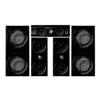
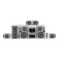
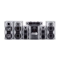
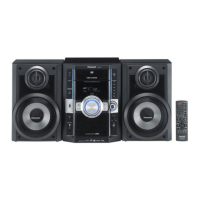
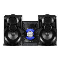
Explanation of the main unit's key buttons and their functions.

7.2. Remote Control Key Buttons Operations

7.4. USB Connection & Operation

7.6. Disc Information

7.6.1. Disc Playability (Media)

Information on which disc types are playable or not.

7.6.2. File Extension Type Support (WMA/MP3/JPEG/MPEG4/DivX)

8 DVD/CD Changer Mechanism Unit

8.1.3. Mechanism Operation

9 Self Diagnosis and Special Mode Setting

9.2. Service Mode Table (For DVD)

9.2.2. Service Mode Table 2

9.2.3. Service Mode Table 3

9.2.4. Service Mode Table 4

9.2.5. Service Mode Table 5

9.2.6. Optical Pickup Unit Breakdown Diagnosis

9.3. Service Mode Table (For Inspection)

9.3.2. Service Mode Table 2

9.3.3. Service Mode Table 3

9.4. DVD Self Diagnostic Function-Error Code

9.4.1. DVD Module Error Code Table

Table listing error codes for the DVD module and their diagnosis contents.

9.4.2. Mechanism Error Code Table

9.4.3. Power Supply Error Code Table

9.4.4. ECC Error Code Table

9.4.5. USB Error Code Table

9.4.6. CD/DVD Changer Mechanism Error Code Table

Error Code

9.4.7. Deck Mechanism Error Code Table

9.5. Sales Demonstration Lock Function

9.6. Service Precautions

9.6.3. DVD Module P.C.B. Reset

10 Assembling and Disassembling

10.2. Main Components and P.C.B. Locations

10.25. Disassembly of Traverse Unit

10.26. Disassembly of Deck Mechanism

10.27. Rectification for Tape Jam Problem

11 Service Position

11.7. Checking & Repairing DVD Module P.C.B.

11.8. Checking & Repairing D-Amp P.C.B.

11.9. Checking & Repairing SMPS P.C.B.

12 Adjustment Procedures

12.1.1. Head Azimuth Adjustment (Deck 1/2)

Step-by-step instructions for adjusting the head azimuth.

12.1.2. Tape Speed Adjustment (Deck 1/2)

Instructions for adjusting the tape speed.

12.1.4. Bias Frequency Adjustment (Deck 1/2)

12.3. Alignment Points

14 Voltage and Waveform Chart

14.2. Main P.C.B.

14.3. Panel P.C.B.

14.4. Deck/Deck Mechanism & Mic P.C.B.

14.5. D-Amp P.C.B.

14.6. SMPS P.C.B.

14.7. Waveform Chart

14.7.2. Waveform 2

14.7.3. Waveform 3

15 Wiring Connection Diagram

16 Block Diagram

16.2. DVD (Servo)

16.3. DVD (Audio)

16.4. DVD (Video)

16.5. Deck

16.6. Audio

16.7. Audio Digital Amp

16.8. Power

18 Schematic Diagram

18.1. DVD Module Circuit

Schematic diagram of the DVD module circuit.

18.2. Main Circuit

18.3. Panel Circuit

18.4. Tact Switch/Mic/Deck Mechanism/USB Relay/USB Circuit

18.5. Deck Circuit

18.6. D-Amp Circuit

18.7. SMPS Circuit

18.8. Speaker/Optical Pickup Unit Circuit

19 Printed Circuit Board

19.2. Main P.C.B.

20 Basic Troubleshooting Guide

20.1. Basic Troubleshooting Guide for Traverse Unit (DVD Module P.C.B)

Guide for troubleshooting issues with the traverse unit/DVD module P.C.B.

21.1. IC2600 (C2CBYY000470): System Control IC

21.2. IC6701 (C0HBB0000064): FL Driver IC

23 Replacement Parts List

23.1. Component Parts List

Related product manuals