EasyManua.ls Logo

Panasonic SA-VKX65GA User Manual

Panasonic SA-VKX65GA
106 pages
To Next Page IconTo Next Page
Page #1 background imageLoading...
Page #1 background image
© Panasonic Corporation 2014. All rights reserved.
Unauthorized copying and distribution is a violation
of law.
PSG1409001CE
DVD Stereo System
Model No. SA-VKX65GA
SA-VKX65GS
Product Color: (K)...Black Type
TABLE OF CONTENTS
PAGE PAGE
1 Safety Precautions----------------------------------------------- 3
1.1. General Guidelines---------------------------------------- 3
1.2. Before Repair and Adjustment ------------------------- 4
1.3. Protection Circuitry---------------------------------------- 4
1.4. Caution For AC Cord (For GS only) ------------------ 5
1.5. Power Supply using SMPS ----------------------------- 6
1.6. Safety Parts Information --------------------------------- 6
2 Warning-------------------------------------------------------------- 7
2.1. Prevention of Electrostatic Discharge (ESD)
to Electrostatically Sensitive (ES) Devices---------- 7
2.2. Precaution of Laser Diode------------------------------- 7
2.3. General description about Lead Free Solder
(PbF)---------------------------------------------------------- 8
2.4. Handling Precautions for Traverse Unit-------------- 8
2.5. Grounding for electrostatic breakdown
prevention --------------------------------------------------- 9
3 Service Navigation----------------------------------------------10
3.1. Service Information-------------------------------------- 10
4 Specifications---------------------------------------------------- 11
5 Location of Controls and Components------------------ 12
5.1. Remote Control Key Button Operation ------------- 12
5.2. Main Unit Key Button Operation---------------------- 13
6 Service Mode----------------------------------------------------- 14
6.1. Service Mode Table ------------------------------------- 14
6.2. Sales Demonstration Lock Function ---------------- 14
6.3. Doctor Mode Table--------------------------------------- 15
6.4. Error Code Table ----------------------------------------- 18
6.5. Self-Diagnostic Mode ----------------------------------- 19
6.6. Self Diagnostic Function-Error Code---------------- 24
6.7. Firmware Version-Up Information-------------------- 25
7 Troubleshooting Guide --------------------------------------- 28
7.1. No Power or No Display-------------------------------- 28
7.2. Bluetooth® Pairing Failure----------------------------- 28
7.3. No Key Function------------------------------------------ 28
Please refer to the original service manual for:
DVD Mechanism Unit (BRS12D), Order No. PSG1408009AE
Speaker system SB-AKX38PN-K, Order No. PSG1402006CE

Table of Contents

Question and Answer IconNeed help?

Do you have a question about the Panasonic SA-VKX65GA and is the answer not in the manual?

Panasonic SA-VKX65GA Specifications

General IconGeneral
TypeMini Hi-Fi System
Total Output Power600 W
DVD PlayerYes
TunerFM/AM
USB PortYes
Remote ControlYes
HDMI OutputNo
Optical Digital InputYes
Coaxial Digital InputNo
BluetoothNo
CD PlayerYes
Number of Channels2.1
Playable MediaCD, DVD, USB

Summary

Safety Precautions

1.1. General Guidelines

General safety guidelines for servicing equipment.

1.2. Before Repair and Adjustment

Procedures and precautions before starting repair or adjustment.

1.3. Protection Circuitry

Information on the unit's protection circuitry and its operation.

1.4. Caution For AC Cord (For GS only)

Specific cautions regarding the AC power cord for GS models.

1.5. Power Supply using SMPS

Details about the Switching Mode Power Supply (SMPS) used.

1.6. Safety Parts Information

List of critical safety components requiring manufacturer's specified parts.

Warning and Precautions

2.1. Prevention of Electrostatic Discharge (ESD)

Techniques to prevent damage to ES devices from static discharge.

2.2. Precaution of Laser Diode

Safety precautions when working with the laser diode.

2.3. Lead Free Solder Information

Information on the use of lead-free solder in the equipment.

2.4. Handling Precautions for Traverse Unit

Precautions for handling the traverse unit, especially the laser diode.

2.5. Grounding for ESD Prevention

Methods for grounding to prevent electrostatic discharge damage.

Service Navigation

3.1. Service Information Overview

Overview of the service manual's content for service personnel.

Controls and Components

5.1. Remote Control Key Button Operation

Explanation of the remote control's buttons and their functions.

5.2. Main Unit Key Button Operation

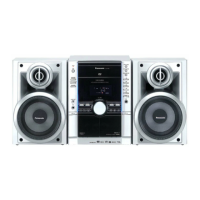
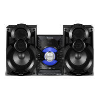
Explanation of the main unit's buttons and their functions.

Service Modes and Diagnostics

6.1-6.3 Service Modes and Functions

Details on service mode table, sales lock, and doctor mode.

6.4-6.6 Error Codes and Diagnostics

Tables for error codes and self-diagnostic functions.

6.7 Firmware Version-Up

Process for updating the unit's firmware.

Troubleshooting Guide

7.1. General Operational Issues

Troubleshooting for power, key function, remote, and USB detection problems.

7.2. Bluetooth and Audio Issues

Troubleshooting for Bluetooth pairing failure and no sound output.

7.7. Diagnostic Checkpoints

Visual guide to key check points on the Power PCB for troubleshooting.

Disassembly and Assembly Instructions

8.1. Disassembly Overview and Flow

Flow chart and component locations for disassembly procedures.

8.2. Cabinet and Panel Disassembly

Instructions for disassembling the top cabinet, front panel, and associated PCBs.

8.3. Internal Component Disassembly

Instructions for disassembling rear panel, main PCB, SMPS, and DVD mechanism.

Service Position and Procedures

9.1. Panel and Music Port P.C.B. Checking

Procedure for checking and repairing the panel and music port PCBs.

9.2. Main P.C.B. and SMPS Module Checking

Procedure for checking and repairing the main PCB and SMPS module.

9.3. Backend P.C.B. Ass'y Checking

Procedure for checking and repairing the backend PCB assembly.

Block Diagrams

10.1. Backend Block Diagram

Block diagram illustrating the backend circuitry.

10.2. System Control Block Diagram

Block diagram of the system control functions.

10.3. Audio Block Diagram

Block diagram of the audio signal path and processing.

10.4. Power Supply Block Diagram

Block diagram of the power supply unit.

Wiring Connection Diagram

Wiring Connection Diagram Overview

Diagram showing the interconnection between different PCBs and units.

Schematic Diagrams

12.1. Schematic Diagram Notes

Notes and symbols used in the schematic diagrams.

12.2-12.5 Backend (DV5U) Circuit Schematics

Detailed schematic diagrams of the backend DV5U circuitry (parts 1-4).

12.6-12.8 Backend Specialized Circuits

Schematic diagrams for backend motor driver, video, and HDMI circuits.

12.9-12.17 Main Unit Circuit Schematics

Schematic diagrams for various main unit circuits (UP, SOC, USB, Tuner, DSP, DAMP, Voltage Regulator, Connector, Bluetooth).

12.18 Panel, USB, Music Port & Mic Circuit Schematics

Schematic diagrams for Panel, USB, Music Port, and Microphone circuits.

Printed Circuit Board Layouts

13.1. Backend and Main PCB Layouts

Component layout diagrams for Backend and Main PCBs (Sides A & B).

13.2. Peripheral PCB Layouts

Component layout diagrams for Panel, USB, Music Port, and Mic PCBs.

Voltage Measurement Reference Tables

14.1. Voltage Measurement Reference

Reference tables for voltage measurements on various PCBs.

Exploded View and Replacement Parts List

15.1. Cabinet Parts Location Diagrams

Diagrams showing the location of cabinet parts, views 1 and 2.

15.3. Packaging Details

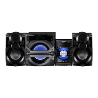
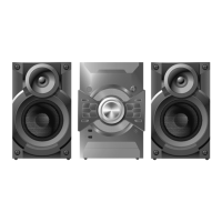
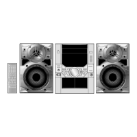
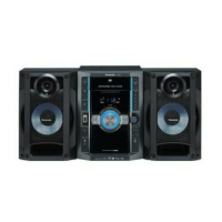
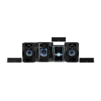
Illustration of the product packaging and included accessories.

15.4. Mechanical Replacement Part List

List of mechanical replacement parts with their details and safety references.

15.5. Electrical Replacement Parts List

List of electrical replacement parts, including ICs and PCBs, with safety references.

Related product manuals