Do you have a question about the Panasonic SA-VK480EE and is the answer not in the manual?
General guidelines for servicing the unit.
Procedure for performing a cold check of leakage current.
Procedure for performing a hot check of leakage current.
Precautions to take before starting repair or adjustment.
Information on the unit's protection circuitry.
Details on critical safety components that require specific replacement parts.
Methods to prevent damage to ES devices from static discharge.
Overview of lead-free solder usage and its properties.
Specific cautions for handling the optical pickup unit safely.
Methods for grounding to prevent electrostatic discharge damage.
General information and notes for service personnel.
Explanation of the function of each key button on the main unit.
Details on which disc media formats are supported and playable.
A summary of available service modes and their functions.
Summary table for the Doctor Mode service function.
Summary table for the Self-Diagnosis modes.
Summary table for DVD-specific service modes.
First part of the Self-Diagnosis Mode Table.
Table listing error codes for the DVD module and their descriptions.
Steps for activating the sales demonstration lock function.
Specific troubleshooting steps for error codes F61 and F76.
Diagram showing the location of components on the SMPS PCB.
List and description of specialized tools and equipment for service.
Steps for assembling the audio digital power amp IC.
Steps for disassembling the switching regulator IC.
Steps for disassembling the rectifier diode D5702.
Steps for disassembling the regulator diode D5803.
Steps for disassembling the regulator diode D5801.
Steps for disassembling the regulator diode D5802.
Steps for disassembling the regulator diode D5803.
Step-by-step instructions for disassembling the traverse unit.
Procedure for checking and repairing the Main PCB.
Procedures for checking and repairing multiple PCBs.
Measurement and adjustment procedures for the cassette deck.
Procedure for adjusting the tape speed.
Voltage and waveform data for the DVD module PCB.
Block diagram for the DVD audio signal processing path.
Schematic diagram for the DVD module circuit.
Diagram showing the layout of the DVD Module PCB.
Pinout and function list for IC2801, the microprocessor.
Pinout and function list for IC6601, the FL driver.
Exploded view diagrams and list of mechanical replacement parts.
| Frequency Response | 20 Hz - 20 kHz |
|---|---|
| Speaker Configuration | 2.0 |
| Number of Discs | 5 |
| Playable Media | CD, CD-R/RW, MP3 |
| Tuner | FM/AM |
| Weight | 8.5 kg |
| Input Types | AUX, CD |
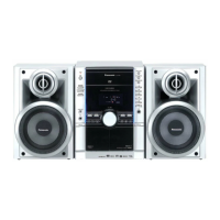
| Type | Mini System |