Do you have a question about the Panasonic SA-VK870EE and is the answer not in the manual?
Details amplifier specifications including output power for different channels and total power.
Specifications for the FM/AM tuner, including preset stations and frequency range.
Specifications for the cassette deck, including auto reverse, track system, and heads used.
Specifies composite and component video output levels and terminal types.
Lists supported media file formats for USB playback (MP3, WMA, JPEG, MPEG4).
Details disc playability information, including playable disc types.
Specifies power supply voltage, frequency, and system model numbers.
General guidelines to be observed during servicing for safety.
Procedures to check leakage current when the unit is unplugged or plugged in.
Precautions before performing repairs and adjustments, including capacitor discharge.
Identifies conditions that might indicate the protection circuitry has operated.
Lists safety-critical parts and the importance of using specified parts.
Techniques to reduce component damage from electrostatic discharge.
Cautions regarding the laser diode, including avoiding disassembly and direct viewing.
Cautions for handling the optical pickup unit to prevent ESD damage and grounding methods.
Explains the functions of buttons on the main unit for operation.
Explains the functions of the remote control buttons for operating the unit.
Details disc playability information, including playable disc types.
Explains how to use the Music Port to enjoy music from a portable audio equipment.
Information about DivX Video-on-Demand content, including registration and playback rules.
Instructions for connecting and playing files from USB mass storage devices.
Summarizes various service modes for checking operations, categorized by DVD and CR14 mechanisms.
Details the service modes available for the DVD section, including special notes.
Provides a table for service mode 1, including mode name, description, FL display, and key operations.
Details service mode 2 for DVD, covering laser drive current measurements.
Details service mode 3 for firmware version, checksum, and initialization.
Details service mode 4 for DVD module PCB firmware version, checks, and resets.
Details service mode 5 for timer checks and resets related to laser and spindle motor.
Procedure for optical pickup self-diagnosis and tilt adjustment to check laser drive current.
Details service modes for the CR14 mechanism, including self-diagnostic and unit service.
Details service modes for CR14 mechanism, including self-diagnostic and unit service.
Details service mode 2 for CR14 mechanism, covering reliability tests.
Lists DVD module error codes, diagnosis, description, FL display, and remarks.
Lists mechanism error codes related to tray loading, servo, tracking, and disc access.
Lists error codes for power supply and digital amplifier abnormalities.
Lists error codes related to USB device connection and communication.
Lists error codes specific to the CD/DVD changer mechanism (CR14).
Procedures for setting the sales demonstration lock function to prohibit disc eject and operation.
Steps for recovery processing after replacing the FLASH ROM IC or DVD Module P.C.B.
Procedure for updating the DVD player firmware using a recovery disc.
Procedure to reset the DVD Module P.C.B. after replacement, including initialization.
General cautions and an index for disassembly procedures, including a note on the CR14 mechanism.
Provides a flowchart outlining the procedure for disassembling the unit's casing and internal parts.
Illustrates the location of main components and printed circuit boards within the unit.
Step-by-step instructions for removing the top cabinet of the unit.
Detailed steps for disassembling the mechanism unit (CR14), including cable detachments.
Step-by-step instructions for removing the rear panel of the unit.
Detailed steps for detaching cables and removing the front panel unit.
Instructions for disassembling multiple related PCBs including Panel, Tact Switch, Sensor, and Side Bar LEDs.
Steps for removing the microphone PCB, including removing the knob and disconnecting cables.
Steps for disassembling the USB PCB, including removing screws and catches.
Steps for disassembling the Music Port PCB, including removing screws and catches.
Instructions for removing the CD lid, including removing a spring and the lid itself.
Steps for disassembling the deck mechanism unit, including removing screws and opening the cassette lid.
Steps for disassembling the deck PCB, including removing screws, desoldering wires, and detaching cables.
Instructions for disassembling the deck mechanism itself.
Steps for replacing the pinch roller and R/P head block assembly.
Steps for replacing the motor, capstan belts, and winding belt in the deck mechanism.
Steps for disassembling the deck mechanism PCB, including desoldering terminals and releasing catches.
Instructions for disassembling the cassette lid.
Procedure to resolve tape jamming issues by rotating the flywheel.
Steps for disassembling the D-Amp PCB, including detaching cables and removing screws.
Steps for replacing the Audio Digital Power Amp IC (IC5000), including desoldering and removal.
Steps for assembling the Audio Digital Power Amp IC (IC5000) onto the heatsink.
Steps for replacing the Audio Digital Power Amp IC (IC5200), including desoldering and removal.
Steps for assembling the Audio Digital Power Amp IC (IC5200) onto the heatsink.
Steps for replacing the Audio Digital Power Amp IC (IC5300), including desoldering and removal.
Steps for assembling the Audio Digital Power Amp IC (IC5300) onto the heatsink.
Steps for replacing the Audio Digital Power Amp IC (IC5400), including desoldering and removal.
Steps for assembling the Audio Digital Power Amp IC (IC5400) onto the heatsink.
Steps for disassembling the Main PCB, including detaching various FFC cables and wires.
Steps for disassembling the SMPS PCB, including detaching wires and removing screws.
Steps for replacing the Switch Regulator IC (IC5701), including desoldering pins.
Steps for assembling the Switch Regulator IC (IC5701) onto the heatsink unit.
Steps for replacing the Switch Regulator Diode (D5702), including desoldering pins.
Steps for assembling the Switch Regulator Diode (D5702) onto the heatsink unit.
Steps for replacing the Regulator Diode (D5801), including desoldering pins and removal from heatsink.
Steps for assembling the Regulator Diode (D5801) onto the heatsink unit.
Steps for replacing the Regulator Diode (D5802), including desoldering pins and removal from heatsink.
Steps for assembling the Regulator Diode (D5802) onto the heatsink unit.
Steps for replacing the Regulator Diode (D5803), including desoldering pins and removal from heatsink.
Steps for assembling the Regulator Diode (D5803) onto the heatsink unit.
Steps for disassembling the AC Inlet PCB, including removing screws, grounding wire, and tie wraps.
Steps for disassembling the DVD Module PCB, including removing screws and ground/shield plates.
Steps for disassembling the traverse unit assembly from the play position.
Steps for assembling the traverse unit assembly, including slotting into guides and fixing FFC wires.
Lists required service fixtures and tools for performing service procedures.
Procedure for checking and repairing the Main PCB, including removing the top cabinet.
Procedures for checking and repairing multiple PCBs: Panel, Deck, Tact Switch, Music Port, and Mic.
Procedures for checking and repairing the D-Amp PCB, including removing the top cabinet and mechanism unit.
Procedures for checking and repairing the AC Inlet PCB and SMPS PCB.
Procedure for checking deck mechanism operation using a cassette tape and applying power.
Procedure for checking deck mechanism operation using a cassette tape and applying power.
Procedure for checking deck mechanism operation without a cassette tape.
Requirements, settings, and preparations for measurements and adjustments on the cassette deck.
Requirements, settings, and preparations for measurements and adjustments on the cassette deck.
Procedure for checking the bias voltage of the cassette deck using a voltmeter.
Procedure for checking the bias frequency of the cassette deck using a digital frequency counter.
Table listing voltage and waveform data for various points on the DVD Module P.C.B.
Table listing voltage and waveform data for various points on the DVD Module P.C.B.
Table listing voltage and waveform data for various points on the D-Amp P.C.B.
Table listing voltage and waveform data for various points on the Main P.C.B.
Table listing voltage and waveform data for Panel, Mic, and Tact Switch PCBs.
Table listing voltage and waveform data for Deck and Deck Mechanism PCBs.
Table listing voltage and waveform data for the SMPS P.C.B.
Displays various waveforms for ICs like IC2900, IC5000, IC5200, etc.
Displays various waveforms for ICs like IC5701, IC5799, IC5899, IC6601, and IC8001.
Illustrations and part numbers for various ICs, transistors, and diodes used in the unit.
Diagram showing wiring connections between different PCBs and components.
Illustrates the functional blocks of the system, including system control, DVD, audio, video, deck, and power.
Block diagram illustrating the system control flow, including the microprocessor and peripheral circuits.
Block diagram detailing the DVD servo system, including optical pickup, motor drive, and focus/tracking control.
Block diagram illustrating the DVD audio signal path, including memory, DAC, and output stages.
Block diagram showing the video signal processing path, including buffers and output signals.
Block diagram of the cassette deck section, illustrating the tape record/playback signal path and motor control.
Block diagram of the audio signal processing path, including the audio signal processor and amplifier stages.
Block diagram of the digital audio amplifier section, showing power amp ICs and speaker output paths.
Block diagram of the power supply section, including transformers, regulators, and DC-DC converters.
Explains symbols, signal lines, and safety notices used in the schematic diagrams.
Detailed schematic diagrams of various circuits, including DVD Module, Main Circuit, Panel, Deck, D-Amp, SMPS, and AC Inlet.
Schematic diagram of the DVD Module circuit, detailing component connections and signal paths.
Schematic diagram of the Main Circuit, showing connections for video, tuner, USB, and main board.
Schematic diagram for the Panel PCB, Side Bar LEDs, and Remote Sensor circuit.
Schematic diagram for Tact Switch, Music Port, Remote Sensor, Mic, and USB circuits.
Schematic diagram of the Deck circuit, including pre-amplifiers, motor control, and head switching.
Schematic diagram of the D-Amp circuit, showing the digital audio power amplifier ICs and speaker outputs.
Schematic diagram of the SMPS (Switch Mode Power Supply) circuit, showing transformers and regulators.
Schematic diagrams for the Deck Mechanism circuit and the AC Inlet circuit.
Layout diagrams for various PCBs including DVD Module, Main, Panel, Deck, D-Amp, SMPS, and AC Inlet.
Layout diagram of the DVD Module Printed Circuit Board (PCB) showing component placement.
Layout diagram of the Main Printed Circuit Board (PCB) showing component placement.
Layout diagrams for the Panel PCB, Side Bar LED PCBs, and Mic/USB PCBs.
Layout diagrams for Tact Switch, Music Port, and Remote Sensor PCBs.
Layout diagrams for the Deck PCB, Deck Mechanism PCB, and AC Inlet PCB.
Layout diagram of the D-Amp Printed Circuit Board (PCB) showing component placement and ICs.
Layout diagram of the SMPS Printed Circuit Board (PCB) showing component placement and cautionary notes.
Guide for troubleshooting common errors like F61, F76, and HDMI output issues.
Guide for troubleshooting errors "F61" and "F76", illustrating checking procedures on SMPS, D-Amp, and Main PCBs.
Provides troubleshooting steps for symptoms like FL display blinking or power-on issues.
Identifies key components on SMPS, D-Amp, and Main PCBs relevant to troubleshooting.
Identifies key components on the SMPS PCB for troubleshooting.
Identifies key components on the D-Amp PCB, including D-AMP ICs and Muting Circuit.
Shows the pin configuration for D-AMP ICs used in the unit.
Identifies key components on the Main PCB, including transistors and DC-DC converters.
Guide for troubleshooting traverse unit issues like distorted picture, no TOC, or abnormal movement.
Guide for troubleshooting HDMI AV output issues, covering no display and resolution problems.
Details the terminal functions of key ICs, including System Control (IC2801) and FL Driver (IC6901).
Details the terminal functions of the IC System Control (IC2801).
Details the terminal functions of the IC FL Driver (IC6901).
Provides exploded views showing the location of cabinet parts and deck mechanism parts.
Exploded view showing the location of cabinet parts and their corresponding numbers.
Exploded view showing the location of parts for the deck mechanism unit.
Diagram showing the packaging of the unit and its accessories.
Lists important safety notices, warnings, and references for replacement parts.
Lists all components with their part numbers, names, descriptions, remarks, and references.
| Brand | Panasonic |
|---|---|
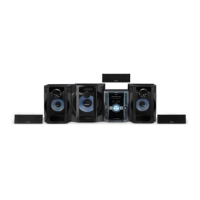
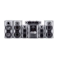
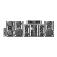
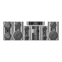
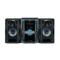
| Model | SA-VK870EE |
| Category | Stereo System |
| Language | English |