Do you have a question about the Panasonic SA-VK680PU and is the answer not in the manual?
General guidelines for safe servicing procedures, including leakage current checks.
Safety measures before performing repairs or adjustments, including capacitor discharge.
Techniques to prevent ESD damage to sensitive devices, including grounding and handling.
Safety warnings regarding laser radiation exposure and handling of the pickup unit.
Care needed when handling the optical pickup unit to prevent static breakdown damage.
Technical specifications for the amplifier, including output power.
Details on supported disc types, including DVD and CD formats, and compatibility.
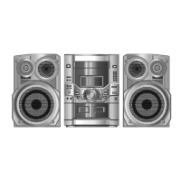
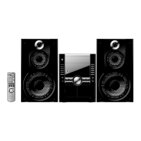
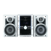
Identifies and explains the function of each button and indicator on the main unit.
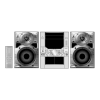
Explains the function of each button on the remote control unit.
Summary of service modes for checking unit function and reliability.
Table detailing Doctor Mode for checking EEPROM and firmware versions.
Table listing DVD module error codes (U702-F899) and their descriptions.
Detailed troubleshooting steps for power-on errors F61 and F76, covering SMPS, D-Amp, and Main PCBs.
A flowchart illustrating the sequence of disassembly for internal components.
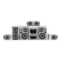
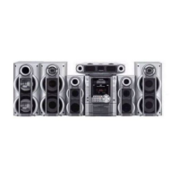
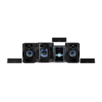
Diagrams showing the location of major components and PCBs within the unit.
Detailed procedure for disassembling the DVD mechanism unit (CR14).
Block diagram showing the audio signal path for the DVD section.
Block diagram of the overall system control and its interconnected components.
Block diagram detailing the audio signal processing and output paths.
Detailed schematic of the DVD module circuit, showing ICs and connections.
Schematic diagram of the main circuit board, including power, control, and interface sections.
Schematic diagram of the cassette deck mechanism control and audio path.
Schematic diagram of the Digital Amplifier circuit, including power stages.
Top and bottom views of the DVD Module PCB with component locations.
Top and bottom views of the Main PCB with component locations.
Top and bottom views of the D-Amp PCB with component locations.
Top and bottom views of the SMPS PCB with component locations.
Pinout and function description for the Microprocessor IC (IC2801).
Exploded views showing the location of mechanical parts for replacement.
List of electrical replacement parts including ICs, transistors, diodes, and passive components.
| Tuner | Yes |
|---|---|
| CD Player | Yes |
| Bluetooth | No |
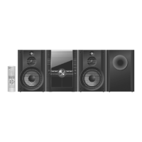
| Remote Control | Yes |
| Playable Media | CD, CD-R, CD-RW |