Do you have a question about the Panasonic SA-VK750EE and is the answer not in the manual?
Detailed schematic diagram of the DVD module circuit, showing connections and components.
Layout of the DVD module printed circuit board (P.C.B.) for component placement.
Comprehensive list of components for the DVD module, including part numbers and descriptions.
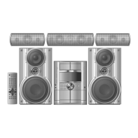
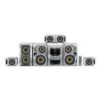
This document serves as a supplement service manual for Panasonic DVD Stereo Systems, specifically covering models SA-VK750EE, SA-VK750GCP, SA-VK850EE, SA-VK850GCP, SA-VK950EE, and SA-VK950GCP, all in a silver finish. It provides additional technical information, primarily focusing on the DVD Module P.C.B. (Printed Circuit Board) for these models, which has undergone changes from previous versions. The manual is intended for experienced repair technicians and emphasizes safety precautions due to the presence of a laser diode and components with special characteristics.
The Panasonic DVD Stereo Systems, as indicated by the model numbers, are designed to provide audio and video playback capabilities, primarily from DVD media. The core functionality revolves around the DVD Module P.C.B., which is responsible for reading and processing data from DVDs. This module integrates various essential components, including a DVD 5.0 LSI (Large Scale Integration) for overall system control, a 64M SDRAM (Synchronous Dynamic Random-Access Memory) for data buffering, and an Audio DAC (Digital-to-Analog Converter) for converting digital audio signals into analog form for output.
The DVD module also incorporates a motor drive IC to control the spindle and traverse motors, which are crucial for disc rotation and laser head movement. A +3.3V DC-DC converter and a +1.2V regulator ensure stable power supply to the various integrated circuits. An EEPROM (Electrically Erasable Programmable Read-Only Memory) is included, likely for storing firmware or configuration settings, though it is noted as "not supplied" in the parts list, suggesting it might be pre-programmed or integrated into another component.
The system's operation involves a complex interplay of signals. DVD RF (Radio Frequency) signals are generated when the laser reads the disc, which are then processed by the LSI. Motor drive signals control the physical movement of the optical pickup unit. Tracking error signals and focus error signals are critical for maintaining accurate laser positioning on the disc, ensuring reliable data retrieval. Additionally, CD and DVD head signals are differentiated, indicating the system's ability to handle both CD and DVD media. Audio and video signals are processed separately, with the audio signals routed through the DAC and video signals prepared for output to a display.
The DVD Module P.C.B. connects to the main circuit of the stereo system via a series of connectors, including FP8101, FP8251, and FP8531. These connectors facilitate the exchange of control signals (CPU-CLK, CPU-CMD, CPU-STAT), power supplies (D+5V, A+5V, M+9V, 2R7V), and processed audio/video outputs (Y/PY/G, CB/PB/B, CR/PR/R, MIX-L, MIX-R, FL, FR, SL, SR, CNT, SW). The system also includes various buffers and switches, such as the LD (Laser Diode) drive switches (Q8551, Q8552, Q8561, Q8562) and a supply control switch (QR8571), to manage the laser and power distribution effectively.
While this manual primarily focuses on the internal components and their interconnections for service purposes, it implicitly highlights several usage features of the DVD Stereo System. The presence of a DVD module indicates the primary function of playing DVD movies and music. The inclusion of an Audio DAC and multiple audio output channels (FL, FR, SL, SR, CNT, SW, MIX-L, MIX-R) suggests support for multi-channel audio, likely for surround sound experiences, enhancing the user's home theater setup. The video output signals (Y/PY/G, CB/PB/B, CR/PR/R) indicate support for various video formats, including component video, which offers higher quality video output compared to composite or S-Video.
The system's ability to differentiate between CD and DVD head signals implies backward compatibility with audio CDs, allowing users to play their existing music collections. The presence of a 16M Flash Memory (IC8651) suggests that the system's firmware can be updated, potentially adding new features, improving performance, or fixing bugs over time. The inclusion of reset ICs (IC8601, IC8606) indicates a mechanism for system recovery in case of software or hardware malfunctions, which can be a useful feature for users experiencing issues.
The detailed schematic diagrams and printed circuit board layouts, though technical, show the intricate design that enables features like precise laser tracking and focus, essential for smooth and uninterrupted playback of optical discs. The various signal lines, such as +B signal lines, motor drive signal lines, DVD RF signal lines, DVD audio signal lines, DVD video signal lines, tracking error signal lines, and focus error signal lines, are all integral to the system's ability to deliver a high-quality multimedia experience. The use of chip inductors and resistors throughout the board suggests a compact and efficient design, contributing to the overall form factor and power consumption of the device.
This service manual is explicitly designed for maintenance and repair, providing critical information for technicians. A key maintenance feature highlighted is the detailed "Replacement Parts List," which specifies the exact part numbers and descriptions for various components within the new DVD Module. This list is crucial for ensuring that only manufacturer-specified parts are used during repairs, which is vital for maintaining the device's safety, performance, and longevity. The manual explicitly warns against interchanging parts for replacement and stresses the importance of using the parts mentioned in Section 4.
The "Special Caution Note" provides essential maintenance instructions. It states that after replacing the DVD Module, it is "necessary to carry out initialization." This indicates a specific post-replacement procedure that technicians must follow, referring to the "Self-diagnosis & Special Mode Setting" section in the main unit's service manual. This initialization process likely calibrates the new module and integrates it correctly with the rest of the stereo system, ensuring proper functionality.
The manual also includes warnings regarding components identified by a "mark," which have "special characteristics important for safety purpose." These include fire-retardant resistors, high-quality sound capacitors, and low-noise resistors. This information guides technicians to pay particular attention to these components during repair, ensuring that their specific properties are maintained to prevent safety hazards or degradation of performance. The warning about the product using a laser diode also points to a critical maintenance consideration, requiring technicians to be aware of laser safety protocols.
The detailed schematic diagrams (Schematic Diagram - 2, 3, 4, 5) and printed circuit board layouts (DVD Module P.C.B. - Side A and Side B) are invaluable maintenance tools. They allow technicians to trace signal paths, identify component locations, and troubleshoot issues effectively. The clear labeling of integrated circuits, transistors, diodes, connectors, coils, and resistors, along with their respective part numbers, simplifies the diagnostic and repair process. For instance, if a specific function fails, a technician can use the schematics to pinpoint the relevant circuit and identify potentially faulty components. The inclusion of remarks like "[M]" for parts supplied by PAVCSG and "[SPG]" for parts supplied by PAVC helps in sourcing the correct replacement parts. The "RTL" (Retention Time Limited) marking for the DVD Module P.C.B. itself is also a critical piece of information for long-term maintenance planning, indicating that the availability of this specific board may be limited after production discontinuation.
| Type | Mini Hi-Fi System |
|---|---|
| Number of speakers | 2 |
| Speaker Type | 2-way |
| Audio formats supported | MP3, WMA |
| Playable disc types | CD, CD-R, CD-RW |
| Disc Compatibility | CD, CD-R, CD-RW |
| CD Player | Yes |
| USB Port | Yes |
| Bluetooth | No |
| Remote Control | Yes |
| Tuner bands | FM |
| Tuner | Digital Tuner |