Do you have a question about the Panasonic SA-VKX95EE and is the answer not in the manual?
Important safety notices, isolation transformer use, lead dress, protective devices, and leakage current checks (cold/hot).
Disconnect power, discharge capacitors, and gradually restore power to prevent damage during servicing.
Explains protection circuitry function and procedures for shorts or impedance issues. Unit requires power cycle.
Safety precautions for AC cord, fuse replacement, and correct wiring, specifically for GS models.
Identifies the SMPS module and lists safety parts marked for hazard prevention, requiring manufacturer-specified replacements.
Techniques to prevent ESD damage to sensitive devices: grounding, anti-static measures, and proper handling.
Safety measures for servicing laser diodes: avoid disassembly, unauthorized adjustments, and direct viewing.
Information on lead-free solder and precautions for handling the traverse unit's optical pickup to prevent ESD damage.
Methods for grounding worktables and human bodies to prevent electrostatic discharge damage to components.
Manual provides technical information for service personnel; orders via parts list, not reference numbers.
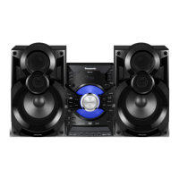
Details amplifier, tuner, USB, Bluetooth, video, disc, and general specifications including power and dimensions.
Explains the function of each button on the remote control for unit operation, including playback and menu controls.
Details the operation of main unit buttons for power, source selection, sound effects, and playback controls.
Describes various service modes like error code display, clearing errors, cold start, and Opecon version display.
Instructions for entering and canceling the sales demonstration lock mode to limit unit functionality for display.
Details Doctor Mode functions: firmware version, cold start, traverse/loading tests, and volume/display checks.
Lists error codes for Power Supply, Bluetooth, Mechanism, and DVD Modules with diagnosis contents and key operations.
Explains self-diagnostic modes for DVD module: error checks, jitter, laser drive settings, timers, and firmware verification.
Flowcharts for common issues: no power, Bluetooth pairing failure, key function, remote control, USB detection, and no sound.
Identifies specific check points for power supply components like fuses and capacitors, including voltage readings.
Lists screw types used and provides a flowchart for the disassembly sequence of major components.
Illustrates the physical location of major components and printed circuit boards (PCBs) within the unit.
Step-by-step instructions for removing the top cabinet, front panel unit, and detaching associated cables.
Guides for disassembling Panel/Music Port PCB, Bluetooth PCB, USB PCB, and Mic PCB assemblies.
Instructions for removing the rear panel, fan unit, and the SMPS module.
Steps to detach main PCB assembly, including FFCs and cables, and disassemble the DVD mechanism unit.
Guide for removing the backend PCB assembly, FFCs, and the DVD mechanism unit.
Procedures for checking Panel/Main PCB and Backend PCB assemblies after reassembly, focusing on cable connections.
Illustrates the backend circuitry, including optical pickup, DVD/CD switching, HDMI transmitter, and PCB connections.
Shows the system control flow, microprocessor, USB switches, panel, and Bluetooth PCB interactions.
Details the audio signal path, from AUX/Music Port input through DSP to digital amplifiers and speakers.
Diagram of the power supply system, including AC inlet, SMPS module, and various voltage regulators.
Visual representation of how different PCBs (Panel, USB, Mic, Backend, Main) are interconnected via connectors.
Explains notes for schematic diagrams, including safety marks, component identification, and units for measurements.
Detailed schematics for the Backend (DV5U) circuit, presented in four parts (1/4 to 4/4), covering various functions.
Schematic diagram for the backend motor driver, showing connections to loading and traverse mechanisms.
Schematics for backend video output driver and HDMI transmitter, detailing signal paths and components.
Schematics for Main (UP), SOC, USB, Tuner/AUX, DSP, DAMP, VREG Fan, and Connector circuits.
Schematics for Panel, Music Port, Microphone, and USB circuits, detailing display, audio input, and connectivity.
Shows the component layout of the Backend PCB assembly (Side A and Side B) with reference designators.
Illustrates the component layout on Side A and Side B of the Main PCB assembly, indicating ICs and connectors.
Displays the PCB layouts for Panel, USB, and Music Port boards, showing component placement.
Shows the PCB layout for the Microphone circuit, including component placement for mic amplifiers and volume controls.
Guidelines for voltage measurements: standard values, potential errors, and reference information.
Tables detailing voltage measurements for various reference points on the Backend PCB across PLAY and STANDBY modes.
Tables providing voltage measurements for Main PCB components (IC1001, IC2100, etc.) in PLAY and STANDBY modes.
Voltage measurements for Mic and Panel PCBs, listing values for various transistors and ICs in PLAY/STANDBY modes.
Exploded views showing the location of cabinet parts, including chassis, panels, and various internal PCBs.
Diagram illustrating unit packaging, showing main units, protective materials, and accessories bag contents.
List of mechanical replacement parts with part numbers, descriptions, quantities, and remarks for assembly.
List of electrical replacement parts including PCBs, ICs, transistors, diodes, resistors, capacitors, and connectors.
| Type | Mini Hi-Fi System |
|---|---|
| Power Output | 100 W |
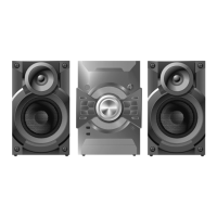
| Number of Channels | 2.1 |
| DVD Player | Yes |
| Tuner | FM/AM |
| USB Port | Yes |
| Dolby Digital | Yes |
| DTS | Yes |
| Bluetooth | No |
| CD Player | Yes |
| Playable Media | CD, DVD, MP3, WMA |