© Panasonic Corporation 2014. All rights reserved.
Unauthorized copying and distribution is a violation
of law.
PSG1409002CE
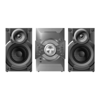
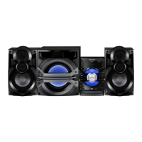
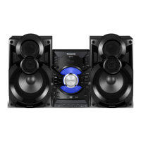
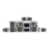
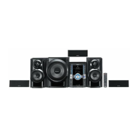
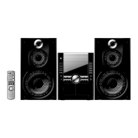
DVD Stereo System
Model No. SA-VKX25EE
SA-VKX25GA
SA-VKX25GS
Product Color: (K)...Black Type
TABLE OF CONTENTS
PAGE PAGE
1 Safety Precautions----------------------------------------------- 3
1.1. General Guidelines---------------------------------------- 3
1.2. Before Repair and Adjustment ------------------------- 4
1.3. Protection Circuitry---------------------------------------- 4
1.4. Caution For AC Cord (For GS only) ------------------ 5
1.5. Power Supply using SMPS ----------------------------- 6
1.6. Safety Parts Information --------------------------------- 6
2 Warning-------------------------------------------------------------- 7
2.1. Prevention of Electrostatic Discharge (ESD)
to Electrostatically Sensitive (ES) Devices---------- 7
2.2. Precaution of Laser Diode------------------------------- 7
2.3. General description about Lead Free Solder
(PbF)---------------------------------------------------------- 8
2.4. Handling Precautions for Traverse Unit-------------- 8
2.5. Grounding for electrostatic breakdown
prevention --------------------------------------------------- 9
3 Service Navigation----------------------------------------------10
3.1. Service Information-------------------------------------- 10
4 Specifications---------------------------------------------------- 11
5 Location of Controls and Components------------------ 12
5.1. Remote Control Key Button Operation ------------- 12
5.2. Main Unit Key Button Operation---------------------- 13
6 Service Mode----------------------------------------------------- 14
6.1. Service Mode Table ------------------------------------- 14
6.2. Sales Demonstration Lock Function ---------------- 14
6.3. Doctor Mode Table--------------------------------------- 15
6.4. Error Code Table ----------------------------------------- 18
6.5. Self-Diagnostic Mode ----------------------------------- 19
6.6. Self Diagnostic Function-Error Code---------------- 24
6.7. Firmware Version-Up Information-------------------- 25
7 Troubleshooting Guide --------------------------------------- 28
7.1. No Power or No Display-------------------------------- 28
7.2. Bluetooth® Pairing Failure----------------------------- 28
7.3. No Key Function------------------------------------------ 28
Please refer to the original service manual for:
DVD Mechanism Unit (BRS12D), Order No. PSG1408009AE
Speaker system SB-AKX18PN-K, Order No. PSG1401008CE