Do you have a question about the Panasonic SA-VK880PU and is the answer not in the manual?
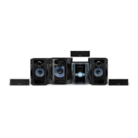
| Number of Channels | 5.1 |
|---|---|
| DVD Player | Yes |
| Tuner | AM/FM |
| USB Port | Yes |
| CD Player | Yes |
| Bluetooth | No |
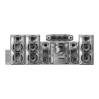
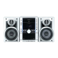
| Type | Mini HiFi System |
| Playable Media | CD, DVD, MP3, WMA |
General guidelines for servicing, safety checks, and lead dress observation.
Procedures for performing cold and hot leakage current checks to prevent shock hazards.
Procedures for discharging capacitors and avoiding short circuits before repair.
Techniques to prevent component damage from static electricity during servicing.
Summarizes various service modes and their activation methods.
Explains self-diagnosis modes for mechanism and traverse unit unlocking.
Lists error codes for HDMI/DVI, SRM, and FLASH ROM issues.
Procedures for checking SMPS, D-Amp, and Main P.C.B. when F61/F76 errors occur.
Block diagram illustrating the relationship between SMPS, D-Amp, and Main P.C.B. for error diagnosis.
Identifies key components and circuits on the SMPS Printed Circuit Board.
Provides a step-by-step procedure for disassembling the unit's casing and internal parts.
Illustrates the location of major components and printed circuit boards within the unit.
Overview of exploded views for cabinet parts and their replacement part numbers.