Do you have a question about the Panasonic SB-AK450 and is the answer not in the manual?
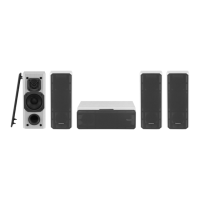
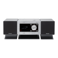
This document outlines the service and maintenance procedures for the SB-AK450PL Speaker System, a component of the Panasonic SC-AK450PL-K and SC-AK450GCP-K systems. The manual is intended for experienced repair technicians, emphasizing safety precautions due to potential hazards associated with electrical products. It provides detailed instructions for disassembling, reassembling, and replacing key components, ensuring proper servicing and optimal performance of the speaker system.
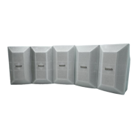
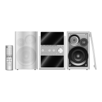
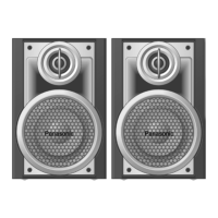
The SB-AK450PL speaker system is designed as a 3-way, 3-speaker bass-reflex unit, featuring a woofer, tweeter, and super tweeter. The system is engineered to deliver high-quality audio output when paired with its recommended main unit. The speakers are designed identically, meaning there is no specific left or right channel orientation required for placement, offering flexibility in setup. However, it is crucial to connect the speaker cables correctly, ensuring the right speaker is connected to the right terminal and the left speaker to the left terminal, and that the load impedance of any speaker used with the unit is 3 Ω. The manual explicitly states that only the supplied speakers should be used, as using other speakers could damage the unit and negatively affect sound quality.
For optimal performance and longevity, several usage features and recommendations are highlighted. Speakers should be placed at least 10mm away from the main system to ensure proper ventilation. These speakers do not have magnetic shielding, so they should not be placed near televisions, personal computers, or other devices that are easily influenced by magnetism, to prevent interference. Users are cautioned that playing sound at high levels over extended periods can damage the speakers and shorten their useful life. To avoid damage, it is recommended to reduce the volume when playing distorted sound or when adjusting sound quality. The front net of the speakers cannot be removed.
Maintenance features are extensively covered through detailed disassembly and assembly procedures. The manual provides a "Disassembly Flow Chart" that guides technicians through the process of disassembling the casing and internal parts for inspection and servicing. To reassemble the unit, technicians are instructed to reverse the steps shown in the chart.
The disassembly process begins with the rear cabinet assembly. Technicians must remove four screws from the front panel, then insert a flathead screwdriver into designated grooves to push and detach the front panel. Following this, the (+) red and (-) black wires connected to the woofer must be detached.
Further disassembly steps are provided for individual components:
The manual also includes a "Connection of the Wiring Diagram" section, which provides a visual guide for correctly connecting the internal wiring of the speaker components (piezo, tweeter, and woofer) to ensure proper functionality. This diagram shows the specific color-coded wires (black, red, blue, gray) and their respective positive (+) and negative (-) terminals for each speaker component.
A critical warning is issued regarding the use of this service information: it is designed for experienced repair technicians only. Non-technical individuals attempting to service the product could face potential dangers. Products powered by electricity should only be serviced or repaired by experienced professional technicians, as any attempt by others could result in serious injury or death. Technicians are also advised that some chassis components may have sharp edges, requiring careful handling during disassembly and servicing.
When replacing components, technicians must use original screws and ensure they are placed in the correct locations. The manual lists the part numbers for different screw types used in the assembly. Furthermore, when replacing any components, technicians must use only manufacturer-specified parts as shown in the replacement parts list. Parts supplied by PAVCSG are specifically marked in the remarks columns.
The document also includes exploded views of the cabinet and packaging, providing visual aids for identifying parts and understanding the assembly structure. The "Cabinet Parts Location" diagram helps technicians locate various components such as the rear cabinet assembly, front panel assembly, wire assembly (piezo), spec label, leg cushion, screws, woofer, and tweeter. The "Packaging" diagram illustrates how the speakers are packed with polyfoam components (Polyfoam A and Polyfoam B) and Miramat, ensuring safe transport and storage.
In summary, the SB-AK450PL Service Manual is a comprehensive guide for professional technicians, detailing the intricate processes of maintaining, repairing, and assembling the speaker system. It emphasizes safety, correct component usage, and precise assembly/disassembly techniques to ensure the longevity and optimal audio performance of the Panasonic SB-AK450PL speakers.
| Brand | Panasonic |
|---|---|
| Model | SB-AK450 |
| Category | Speaker System |
| Language | English |