Do you have a question about the Panasonic SB-HC950 and is the answer not in the manual?
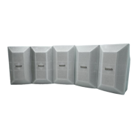
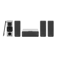
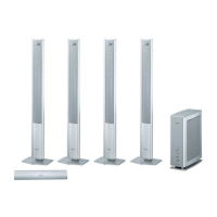
Details the breakdown of speaker combinations used in main unit systems.
Provides information regarding packaging conditions for the speaker system.
Outlines the procedure for disassembling the casing and internal parts for inspection.
Step-by-step guide to remove the rear cabinet of the speaker system.
Instructions for detaching and removing the first woofer unit.
Instructions for detaching and removing the second woofer unit.
Procedure for removing the terminal jack from the speaker.
Illustrates the location of various cabinet parts with reference numbers.
This document outlines the service and maintenance procedures for the SB-HC950P speaker system, a component designed to integrate into various home theater and music systems. It provides comprehensive instructions for assembly, disassembly, and connection, ensuring proper setup and troubleshooting.
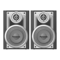
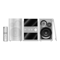
The SB-HC950P is a 2-way, 2-speaker system featuring a bass reflex design. It is primarily intended for use as a center speaker within a larger home theater setup, as indicated by its inclusion in various speaker system combinations like the SB-PT950P-K and SB-PT1050P-K. These combinations typically include front, surround, and center speakers, with the SB-HC950P-K specifically serving the center channel role. Its design focuses on delivering clear audio for dialogue and central sound elements in a multi-channel audio environment.
The manual emphasizes several key aspects for optimal use and performance of the SB-HC950P speaker system:
The service manual provides detailed instructions for disassembling and reassembling the SB-HC950P, which are essential for internal inspection, repair, and component replacement.
This structured approach ensures that service personnel can efficiently and safely perform maintenance, troubleshooting, and repairs on the SB-HC950P speaker system, maintaining its performance and longevity.
| Total Power Output | 1000W |
|---|---|
| Remote Control | Yes |
| Type | Speaker System |
| Configuration | 5.1 |
| Inputs | Optical |
| Bluetooth | Yes |