EasyManua.ls Logo

Panasonic SB-HC750P - User Manual

Panasonic SB-HC750P
11 pages
Print Icon
To Next Page IconTo Next Page
Loading...
Type 1 way, 2 speaker system (Bass reflex)
Speaker unit(s) Impedance 6
1. Full range 6.5 cm (2-1/2”) cone type
2. Full range 6.5 cm (2-1/2”) cone type
Input power (IEC) 250 W* (Max)
Output sound pressure 82 dB/W (1.0 m)
Frequency range 80 Hz - 25 kHz (-16 dB)
96 Hz - 22 kHz (-10 dB)
Dimensions (W x H x D) 270mm x 94mm x 95 mm
1 System Combination
2
1.1. System Breakdown
2
1.2. Packaging Information
2
2 Assembling and Disassembling
3
2.1. Disassembly flow chart
3
2.2. Disassembly of Rear cabinet assembly
4
2.3. Disassembly of Woofer 1
5
© 2007 Matsushita Electric Industrial Co. Ltd.. All
rights reserved. Unauthorized copying and
distribution is a violation of law.
SB-HC750P
Colour
(K)... Black Type
(S)... Silver Type
(10-5/8” x 3-11/16” x 3-3/4”)
Mass 1.3kg(2.9lbs)
Notes :
1. Specifications are subject to change without notice.
Mass and dimensions are approximate.
2. Total harmonic distortion is measured by the digital spectrum
analyzer.
* : Rating with low-cut filter equipped amplifier.
2.4. Disassembly of Woofer 2
5
3 Connection of the Speaker Cables
6
4 Connection of the Wiring Diagram
9
5 Exploded view
10
5.1. Cabinet Parts Location
10
6 Replacement Parts List
11
Speaker System
Specification
CONTENTS
Page Page
ORDER NO. MD0702007CE
A6
Question and Answer IconNeed help?

Do you have a question about the Panasonic SB-HC750P and is the answer not in the manual?

Overview

This document describes the SB-HC750P speaker system, a component of various Panasonic home theater systems.

Function Description

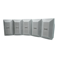
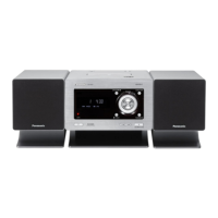
The SB-HC750P is a 1-way, 2-speaker bass-reflex system designed to provide audio output for home theater setups. It functions as a center speaker within larger speaker systems like the SB-PT750P-K or SB-PT650P-S, which include front, surround, and subwoofer components. The speaker is designed to be connected to an amplifier with a low-cut filter for optimal performance.

Important Technical Specifications

  • Type: 1-way, 2-speaker system (Bass reflex)
  • Speaker Unit(s): Two 6.5 cm (2-1/2") cone type full-range speakers.
  • Impedance: 6 Ω
  • Input Power (IEC): 250 W* (Max) (*Rating with low-cut filter equipped amplifier.)
  • Output Sound Pressure: 82 dB/W (1.0 m)
  • Frequency Range:
    • 80 Hz - 25 kHz (-16 dB)
    • 96 Hz - 22 kHz (-10 dB)
  • Dimensions (W x H x D): 270mm x 94mm x 95 mm (10-5/8" x 3-11/16" x 3-3/4")
  • Mass: 1.3 kg (2.9 lbs)
  • Color Options: Black Type (K) and Silver Type (S).

Notes on Specifications:

  • Specifications are subject to change without notice.
  • Mass and dimensions are approximate.
  • Total harmonic distortion is measured by a digital spectrum analyzer.

Usage Features

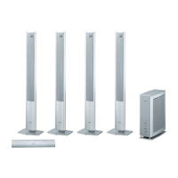
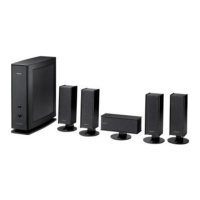
System Combination: The SB-HC750P-K (Black Type) is part of the SB-PT750P-K speaker system, which is used with the SC-PT750P/PC-K main unit. This system includes:

  • Front speakers: SB-HF750P-K (x2)
  • Surround speakers: SB-HS750P-K (x2)
  • Center speaker: SB-HC750P-K (x1)
  • Subwoofer: SB-HW750P-K (x1)

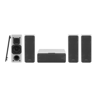
The SB-HC750P-S (Silver Type) is part of the SB-PT650P-S speaker system, which is used with the SC-PT650P/PC-S main unit. This system includes:

  • Front speakers: SB-HF650P-S (x2)
  • Surround speakers: SB-HS650P-S (x2)
  • Center speaker: SB-HC750P-S (x1)
  • Subwoofer: SB-HW750P-S (x1)

Connection of Speaker Cables:

  • Always connect speaker cables before connecting the AC power supply cord.
  • The load impedance of any speaker used with this unit must be 6 Ω.
  • Ensure correct polarity: connect positive (+) (white) wires to positive (+) terminals and negative (-) (blue) wires to negative (-) terminals.
  • Twist and pull off the vinyl tip of speaker cords. If cords lack vinyl tips, connect bare ends directly to terminals, ensuring no unravelled wires.
  • Insert the wire into the rear panel of the unit and close the lever.
  • Caution: Never short-circuit positive (+) and negative (-) speaker wires to prevent damage to circuitry. Incorrect polarity or short-circuiting can damage the speakers.

Positioning the Speakers:

  • Place speakers on flat, secure bases.
  • Avoid placing speakers too close to floors, walls, and corners, as this can result in excessive bass.
  • Cover walls and windows with thick curtains to improve sound.
  • Maintain at least 10 mm (13/32") clearance from the system for proper ventilation.
  • Place the front, center, and surround speakers at approximately the same distance from the seating position.
  • Center Speaker (SB-HC750P): Place on a rack or shelf. Avoid placing directly on the television, as speaker vibration can disrupt the picture.
  • Subwoofer: Place to the right or left of the television, on the floor or a sturdy shelf, ensuring it won't cause vibration. Maintain about 30 cm (1113/16") from the television.
  • Main Unit/Digital Transmitter: Position with at least 5 cm (2") of space on all sides for proper ventilation and airflow.
  • Universal Dock for iPod: Position near the main unit.
  • Wireless System: Place within approximately 10 m (33 ft) from the main unit. Avoid placing the wireless system or digital transmitter in a metal cabinet or bookshelf.
  • Interference Avoidance: To prevent interference, maintain the following distances between the wireless system and other electronic devices that use the same radio frequency (2.4 GHz band):
    • Wireless LAN: approx. 2 m (6-1/2 ft)
    • Cordless phone and other electronic devices: approx. 2 m (6-1/2 ft)
    • The wireless system will automatically seek a clear channel if interference occurs, causing the wireless link indicator ("W1") to flash and a brief audio interruption. This is normal operation. If interference persists, move other devices or the wireless system.

Speaker Use Notes:

  • Use only the supplied speakers. Using other speakers can damage the unit and negatively affect sound quality.
  • Avoid playing sound at high levels over extended periods to prevent damage and shorten speaker life.
  • Reduce volume when:
    • Playing distorted sound.
    • Speakers reverberate due to a record player, noise from FM broadcasts, or continuous signals from an oscillator, test disc, or electronic instrument.
    • Adjusting sound quality.
    • Turning the unit on or off.
  • Irregular Coloring on Television: The front and center speakers are designed for close proximity to a television, but some TVs or setups may experience picture effects. If this occurs, turn the television off for about 30 minutes to allow the TV's demagnetizing function to correct the problem. If it persists, move the speakers further away.
  • Caution: The main unit and supplied speakers must be used only as indicated in the setup. Failure to do so may damage the amplifier and/or speakers, and poses a risk of fire. Consult a qualified service person if damage or performance changes occur.
  • Do not attempt to attach these speakers to walls using methods other than those described in this manual.
  • Do not touch the front netted area of the speakers; hold by the sides.

Maintenance Features

Assembling and Disassembling:

  • Some chassis components may have sharp edges; exercise caution during disassembly and servicing.
  • The manual describes procedures for checking major printed circuit boards and replacing main components.
  • For reassembly, reverse the disassembly procedures. Special reassembly procedures are described only when required.
  • Refer to the "Parts Location and Replacement Parts List" (Section 6) for part numbers.
  • Caution: Original screws should be used for reassembly.
  • Disassembly Flow Chart:
    1. Rear cabinet assembly
    2. Woofer 1
    3. Woofer 2
    • To assemble the unit, reverse these steps.

Disassembly of Rear Cabinet Assembly:

  1. Remove 6 screws (a x 6).
  2. Upset the speaker unit.
  3. Insert a steel rule into the bottom corner of the rear cabinet assembly.
  4. Apply light force to push out the front panel.
    • Caution: Do not exert strong force, as it may damage the rear cabinet assembly.
  5. Detach the blue (-) wire from woofer 1 and the white (+) wire from woofer 2.

Disassembly of Woofer 1:

  1. Detach the blue (+) wire.
  2. Remove 4 screws (a x 4).

Disassembly of Woofer 2:

  1. Detach the blue (-) wire.
  2. Remove 4 screws (a x 4).

Replacement Parts List:

  • Important Safety Notice: When replacing components, use only manufacturer's specified parts shown in the parts list.
  • [M] markings in the Remarks columns indicate parts supplied by PAVCSG.
Ref. No. Part No. Part Name & Description Remarks
CABINET AND CHASSIS
1 RYPX0183-K FRONT PANEL ASS'Y [M]
2 RYKX0344-K REAR CABINET ASS'Y [M] K
2 RYKX0344-S REAR CABINET ASS'Y [M] S
3 RGNX0432-S1 SPEC LABEL [M] S
3 RGNX0524-K SPEC LABEL [M] K
4 RKA0072-KJ LEG RUBBER [M]
5 XTB3+10GFJ SCREW [M]
6 REEX0712 TRANSIT WIRE [M]
SPEAKER
SP1 EAS65P122B SPEAKER [M]

Panasonic SB-HC750P Specifications

General IconGeneral
BrandPanasonic
ModelSB-HC750P
CategorySpeaker System
LanguageEnglish

Related product manuals