TC-14A04A / TC-20A04A
- 6 -
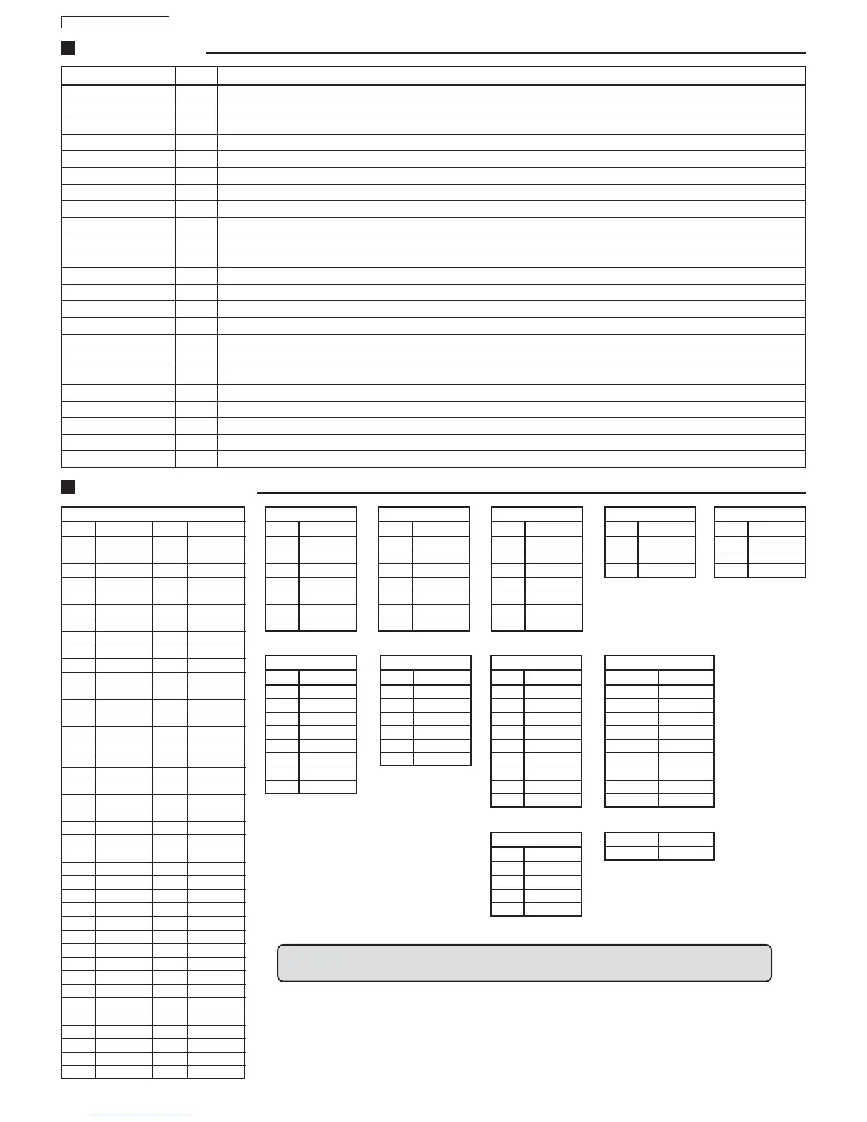
Pin Voltage
1 3,3
2 21.2mV
32
40
5 2,56
6 97.5mV
70
8 2,3
98
10 5
11 3,3
12 3,9
13 0
14 4
15 11.6mV
16 1,3
17 1,3
18 1,9
19 1,9
20 3,9
21 3,8
22 146.7mV
23 181.3mV
24 181.3mV
25 0
26 1,3
27 2,5
28 3,7
29 3,7
30 0,6
31 0,5
32 2,3
33 2,8
34 1,6
35 1,5
36 198mV
37 0,4
38 2,7
39 8
40 3,6
IC VOLTAGE TABLES
Pin Voltage
41 0
42 3,8
43 0
44 3,3
45 0
46 3,6
47 2,9
48 3,5
49 4,4
50 2,5
51 2,7
52 2,7
53 2,7
54 2
55 5,3
56 3
57 3
58 3
59 3,3
60 0
61 3,3
62 28.5mV
63 1,9
64 1,9
65 0
66 3,3
67 105mV
68 4,7
69 5
70 3,2
71 2,3
72 3
73 55.9mV
74 0
75 0
76 3,7
77 0
78 0
79 0
80 0
IC601
Pin Voltage
1 0,3V
2 15,6V
3 -14V
4 -15,6V
5 67mV
6 16,5V
7 0,3V
IC451
Pin Voltage
1 183V
2
3 22,7V
4 22,3V
5 96mV
6 1,5V
7 0,52V
IC801
Pin Voltage
1 10,5V
2 10,5V
3 6,5V
4 4,3mV
5 6,3V
68V
75V
IC851
Pin Voltage
1 7,3mV
2 7,3mV
3 7,3mV
4 7,3mV
5 3,8V
6 3,8V
7 0,2V
85V
IC1103
Pin Voltage
1 11,22V
2 0,26V
3 6,6mV
4 0,23V
5 0,2V
6 1,46V
7 6,6mV
8 0,25V
9 50mV
IC2301
Pin Voltage
15V
2 6,4mV
3 1,27V
4 3,3V
5 6,4mV
65V
IC1201
Pin Voltage
1 0,25V
2 0,25V
3 1,9V
4 1,9V
X101
Pin Voltage
1 141V
2 8,5V
3 -8,7mV
IC802
Pin Voltage
1 10,4V
25V
3 -3,9mV
IC880
Pin Voltage
(V2) 1 22,5mV
(V1) 2 23mV
(P2) 5 180V
(PT) 7 170V
(P1) 8 168V
(S6) 11 0,5V
(S1) 12 0,2V
(S2) 15 0,7V
(S3) 17 0,2V
T801
TPA10 142V
TPA11 11,2V
BO 58 Blue output
VDDA 59 analog supply of Teletext decoder and digital supply of TV-processor (3.3 V)
VPE 60 OTP Programming Voltage
VDDC 61 digital supply to core (3.3 V)
OSCGND 62 oscillator ground supply
XTALIN 63 crystal oscillator input
XTALOUT 64 crystal oscillator output
RESET 65 reset
VDDP 66 digital supply to periphery (+3.3 V)
P1.0/INT1 67 port 1.0 or external interrupt 1 input
P1.1/T0 68 port 1.1 or Counter/Timer 0 input
P1.2/INT0 69 port 1.2 or external interrupt 0 input
P1.3/T1 70 port 1.3 or Counter/Timer 1 input
P1.6/SCL 71 port 1.6 or I2C-bus clock line
P1.7/SDA 72 port 1.7 or I2C-bus data line
P2.0/TPWM 73 port 2.0 or Tuning PWM output
P2.1/PWM0 74 port 2.1
P2.2/PWM1 75 port 2.2
P2.3/PWM2 76 port 2.3
P2.4/PWM3 77 port 2.4
P2.5/PWM4 78 port 2.5
SYNC_FILTER 79 CVBS (i.e. P0.6/CVBS) Sync filter input: This pin should be connected to VSSA via a 100 nF capacitor.
P3.0/ADC0 80 port 3.0 or ADC0 input
All voltage measurements were made in POWER ON mode, with 127V 60Hz power
source and Color Bars Video Pattern.
Symbol Pin Description
IC601 - PINOUT
 Loading...