- 11 -
TC-14A04A / TC-20A04A
ADJUSTMENTS
ITEM / PREPARATION PROCEDURE
2- VIF DETECTOR OUTPUT LEVEL
CONFIRMATION
CONFIRMATION:
1. Install the chassis in the VIF calibration JIG and tune in a
63 dBU colorbar pattern (75Ω opened).
2. Connect the oscilloscope in TPA31.
3. Confirm that the output video sign is 1.05 ± 0.15 Vp-p in
TPA 31.
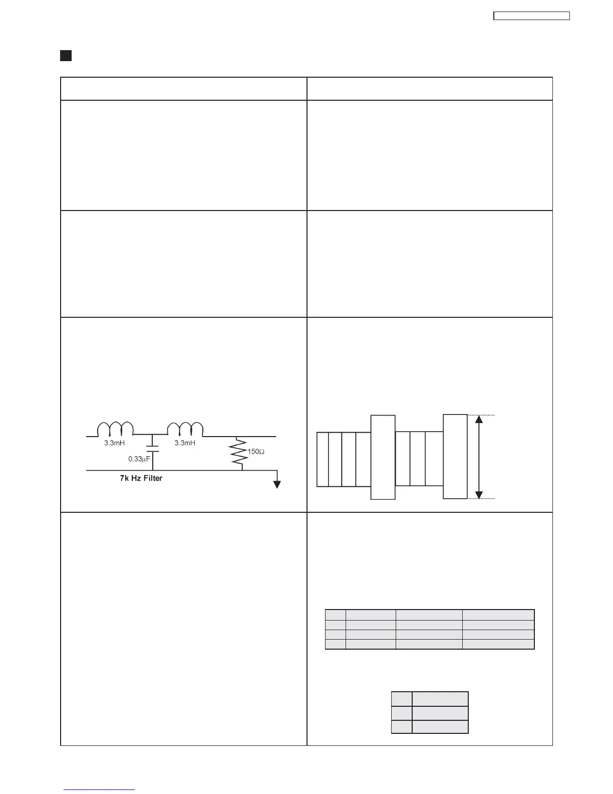
3- BUZZING CONFIRMATION
(AUDIO CIRCUIT)
1. Connect the oscilloscope with a 7kHz filter between A22-
2 and A22-3 speakers terminals .
2. Adjust the sound to maximum.
3. Adjust AVL: OFF
CONFIRMATION:
1. Supply a colorbar signal with local frequency adjusted
and the AFC ON (Channel with sound bearer and without
modulation).
2. Assure that the width in the buzzing waveform is smaller
than 500 m Vp-p.
1- RF AGC ADJUSTMENT
1. Supply a color bar pattern and adjust the RF input signal
of 69 dB µV (75Ω opened channel 07 RF freq.: 175.25
MHz).
2. Connect the digital multimeter in TPA15.
ADJUSTMENT:
1. Select RF AGC on CHK2 service mode.
2. Adjust "RF AGC" by pressing VOL(+) or (-) until obtaining
2.2±0.1V in TPA15.
3. Increase the input level by +2 dB and confirm that the
voltage decreases in TPA15.
CONFIRMATION
1. Connect a voltage meter between TPA10 and ground.
Confirm that the voltage +B is within a range of 140.5V±
1.5V
2. Connect a high frequency voltage meter (VRMS) among
the heater, and confirm that the voltage is as below:
3. Connect the high voltage meter in the CRT anode pin,
and confirm that the high voltage is within [A] range.
4- ANODE AND HEATER VOLTAGE CONFIRMATION
1. Supply a crosshatch signal.
2. Adjust the current beam to zero. (0 beam).
3. Adjust “SCREEN VR” and “CONTRAST” to minimum.
Nota:
(When using a high voltage meter resistive type, it is
necessary to use an electrostatic meter type to verify the
values)
14" SAMSUNG A34KQW42X 6,30 ± 0,25 Vrms
14" PHILIPS A34EAK01X 6,15 ± 0,25 Vrms
20" SAMSUNG A48KRDB89X 6,30 ± 0,25 Vrms
20" PHILIPS A48EAK01X 6,15 ± 0,25 Vrms
CRT [A]
14” 25,2 ~ 23,0
20” 27,2 ~ 25,0
smaller than
500 m Vp-p
 Loading...