EasyManua.ls Logo

Panasonic TC-20B10P - User Manual

Panasonic TC-20B10P
43 pages
To Next Page IconTo Next Page
Loading...
Service Manual
Order no. DCS - SET2000 - 001- MS
TC-14B10P
TC-20B10P
Chassis MX5Y
Specifications
TV MODEL
Power Source
Power consumption, Max (A)
Antenna Input
Colour System
Tuning System
Channels Receiving
Picture Tube
(Measured Diagonally)
Audio Output
AV Input
Dimensions (W x H x D)
Weight
TC-14B10P
110/220 V AC, 50/60 Hz
automatic switch
80W
75 - VHF/UHF/CATV
NTSC/AUTO/PAL-M/PAL-N
F.S.T
2 to 13 (VHF)
14 to 69 (UHF)
1 to 125 (CATV)
34 cm
3W max (RMS)
1 (front) - 1 (rear)
370 x 351 x 366 mm
9,6 kg
TC-20B10P
110/220 V AC, 50/60 Hz
automatic switch
90W
75 - VHF/UHF/CATV
NTSC/AUTO/PAL-M/PAL-N
F.S.T
2 to 13 (VHF)
14 to 69 (UHF)
1 to 125 (CATV)
48 cm
3W max (RMS)
1 (front) - 1 (rear)
502 x 455 x 471 mm
17 kg
Remote Control Transmiter:
Power Source 3V (2 R6 batteries)
Infrared Length 9500 A (Angstron)
Number of Buttons 27 buttons
Dimensions (W x H x D) (51 x 28 x 150) mm
Wight 55g
Provided accessories
l
1 Remote Control Transmiter
l
1 Balum 300 / 75 (Balum)
l
2 R6 size batteries 1,5V (ABNT/IEC)
l
1 Internal antenna (only for 14 models)
Panasonic
®
Design and specifications are subject to change without notice
Color Television
ENGLISHESPAÑOL
Question and Answer IconNeed help?

Do you have a question about the Panasonic TC-20B10P and is the answer not in the manual?

Panasonic TC-20B10P Specifications

General IconGeneral
BrandPanasonic
ModelTC-20B10P
CategoryTV
LanguageEnglish

Summary

TV Specifications

Model and Core Specifications

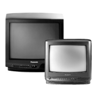
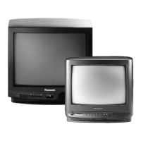
Details TV models, power, antenna, colour system, tuning, and channels.

Picture Tube, Audio, AV, Dimensions, and Weight

Lists picture tube size, audio output, AV input, dimensions, and weight.

Remote Control and Accessories

Specifies remote control and provided accessories.

Safety and Servicing Guidelines

Important Safety Notices

Critical safety warnings for component handling and hazards.

General Servicing Precautions

General guidelines for safe and proper servicing procedures.

Cabinet Opening Procedure

Step-by-step instructions for safely opening the TV cabinet.

User Operation Guide

Control Locations Overview

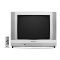
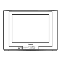
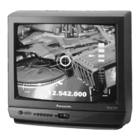
Identifies controls on the front panel, back panel, and remote.

TV Controls and Remote Operation

Explains how to operate TV controls and the remote.

Remote Control Functions and Menus

Remote Channel and Timer Operations

Details channel selection, recall, and timer functions.

Main Menu and Image Icon Operations

Navigation and adjustment within the main and image menus.

Sound Icon Operation

Explains adjustments available via the sound icon menu.

Advanced Operation Features

Language and Preset Icon Settings

How to select language and use preset icons.

Hotel Mode Functionality

Instructions for activating, using, and deactivating Hotel Mode.

Service Adjustments and Calibrations

DAC Control System Operation

Guidance on operating the DAC control system for adjustments.

Serviceman Mode Entry and Exit

Procedures for entering and exiting the serviceman mode.

CHQ Mode Navigation and Options

Details different CHQ modes and their specific options.

Service Mode Parameters

DAC Direct Table and Memory Access

Explains the DAC direct table and memory access methods.

EEPROM Memory Map and Electrical Inspection

EEPROM layout and requirements for electrical inspection.

Voltage Inspection Procedures

Steps for conducting voltage inspections.

Circuit Inspections and Video Calibration

Deflection Circuit and Pre-Adjustments

Inspection of deflection circuits and initial adjustments.

Cut Off, Sound, and Colour Inspections

Procedures for cut-off, sound, and colour control inspections.

Video IF Calibration

Detailed steps for calibrating the Video IF section.

Signal Calibration and Adjustments

Video IF Calibration Details

Continuation of Video IF calibration procedures.

AFT, AGC-RF, and Noise Level Adjustments

Procedures for adjusting AFT, AGC-RF, and noise levels.

Picture Quality Adjustments

Video Output and Sub-Contrast

Adjustments for video output and sub-contrast levels.

Colour Saturation and Sharpness Settings

Procedures for setting colour saturation and sharpness.

Shutdown System Confirmation

Steps to confirm the shutdown system functionality.

Geometry and White Balance Adjustments

Horizontal Width and Centering

Adjustments for horizontal width and centering.

Vertical Height and Centering

Adjustments for vertical height and centering.

White Balance and CRT Cut-Off

Pre-adjustments for white balance and CRT cut-off.

Functional Checks and Focus

Focus Adjustment and Front Panel Checks

Adjusting focus and checking front panel controls.

AV Input and Microprocessor Verification

Checks for AV input terminals and microprocessor.

Standby Operation Verification

Confirming the correct operation of the standby mode.

Operation Verification

Channel Memorization Verification

Verifying automatic and manual channel memorization.

Tuning and Audio Function Checks

Checking channel tuning and audio functionality.

Noise Mute and Blue Screen Confirmation

Verifying noise mute and blue screen behavior.

Purity and Convergence Adjustments

Estatic Convergence Setup

Procedures for static convergence centering and purity.

Dynamic Convergence Adjustment

Steps for dynamic convergence adjustment.

Microscope Verification of Purity

Using a microscope to verify purity adjustments.

Schematic Diagrams

Y Board Schematics (14 & 20)

Circuit diagrams for the Y board for both CRT sizes.

Yoke Board and Deflection Yoke Diagrams

Visuals of the yoke board and deflection yoke connections.

Integrated Circuit Analysis

IC601 Block Diagram

Functional block diagram for IC601.

IC601 Pinout and Functions

Detailed list of IC601 pins and their functions.

Waveform Analysis Guide

Waveform Measurement Instructions

Guide on how to obtain and interpret waveforms.

Sample Waveforms (01-12)

Illustrated waveforms for various test points.

Waveform Analysis (Continued)

Waveform Measurement Guide Updates

Additional instructions for waveform measurement.

Sample Waveforms (13-24)

Illustrated waveforms for additional test points.

Cabinet Part Identification

Exploded View of Cabinet Components

Diagram showing the location of cabinet parts.

Cabinet Replacement Parts

Mechanical Parts List (TC-14 B10 P)

List of mechanical replacement parts for the 14-inch model.

Mechanical Parts List (TC-20 B10 P)

List of mechanical replacement parts for the 20-inch model.

Main Board Component Lists

Main Board Capacitors (TC-14 B10 P)

Replacement parts list for main board capacitors.

Main Board Capacitors (TC-20 B10 P)

Replacement parts list for main board capacitors.

General Component Replacement Parts

Capacitors, Diodes, and ICs Replacement List

Parts list for various electronic components.

Jumpers and Coils Replacement List

Replacement parts for jumpers and coils.

Transistor and Resistor Replacement Parts

Transistor Parts List

List of replacement transistors.

Resistor Parts List

List of replacement resistors.

Resistor and Miscellaneous Parts List

Resistor Replacements (R592-R1126)

Continued list of replacement resistors.

Switches, Transformers, Tuner, Crystals List

Parts list for switches, transformers, tuner, and crystals.

Main Board Parts List (TC-20 B10 P)

Capacitors;Condensers (TC-20 B10 P)

Replacement parts for main board capacitors.

Component Parts List (TC-20 B10 P)

Capacitors, Diodes, ICs (TC-20 B10 P)

Parts for capacitors, diodes, and ICs.

Jumpers and Coils (TC-20 B10 P)

Parts for jumpers and coils.

Transistor and Resistor Parts List (TC-20 B10 P)

Transistors (TC-20 B10 P)

Replacement transistor parts.

Resistors (TC-20 B10 P)

Replacement resistor parts.

Resistor and Miscellaneous Parts (TC-20 B10 P)

Resistors R592-R1126 (TC-20 B10 P)

Continued list of replacement resistors.

Switches, Transformers, Tuner, Crystals (TC-20 B10 P)

Parts for switches, transformers, tuner, and crystals.

Related product manuals