EasyManua.ls Logo

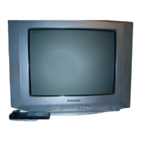
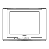
Panasonic TC-20KL03A - User Manual

Panasonic TC-20KL03A
48 pages
To Next Page IconTo Next Page
Loading...
Service Manual
Order DCS - NOV2003 - 001 - MS
TC-20KL03A
TC-29KL03A
Panasonic
®
Color Television
MX5ZB CHASSIS
© 2003 Panasonic da Amazônia S/A
CS Division
Technical Support
TELEVISION
Power source
Consumption
Antenna input jack
Color systems
Tuning system
Channel capability
Picture tube (Diagonal Visual)
Audio system
Video input jack
Audio input jack
Video Outlet
Audio Outlet
Dimension (width, height, depth)
Weight
TC-20KL03A
110/220 V AC, 50/60 Hz automatic switch
79 W
75 ohms - VHF/UHF/CATV
PAL-M/NTSC/PAL-N
F.S.T.
2 to 13 (VHF)
14 to 69 (UHF)
1 to125 (CATV)
Panablack 48 cm
50 W PMPO
1 (back) + 1 (front)
1 (back)
1 (back) + 1 (earphone)
600 x 473 x 487 (mm)
17.7 kg
Supplied Accessories:
• 1 Remote Control Transmitter
• 1 300/75 Balum
• 2 “AA” (or R6) batteries (1.5V; ABNT/IEC)
• 1 Internal antenna (for TC-20KL03A only)
Specifications
Specifications are subject to change without notice. Weight and dimensions shown are approximate.
Remote Control Transmiter:
Power Source 3V (2 AA type batteries)
Infrared Length 9500 A (Angstron)
Number of Buttons 29 keys
Dimensions (W x H x D) (54 x 27 x 135) mm
TC-20KL03A
110/220 V AC, 50/60 Hz automatic switch
120 W
75 ohms - VHF/UHF/CATV
PAL-M/NTSC/PAL-N
F.S.T.
2 to 13 (VHF)
14 to 69 (UHF)
1 to125 (CATV)
Panablack 68 cm
82 W PMPO
1 (back) + 1 (front)
1 (back)
1 (back) + 1 (earphone)
760 x 579 x 512 (mm)
34 kg
Question and Answer IconNeed help?

Do you have a question about the Panasonic TC-20KL03A and is the answer not in the manual?

Panasonic TC-20KL03A Specifications

General IconGeneral
BrandPanasonic
ModelTC-20KL03A
CategoryTV
LanguageEnglish

Summary

Specifications

Important Safety Notice

Safety Precautions for Servicing

Critical safety information regarding component replacement and handling to prevent hazards.

General Guidelines

Servicing Procedures and Precautions

Guidelines for safe servicing, including isolation transformers, lead dress, and CRT handling.

Service Mode Adjustments

Entering Service Mode

Step-by-step instructions to access the television's service mode.

CHK1 - Options Adjustment

Adjusting various option codes within the service menu for specific functionalities.

Adjustments

Required Test Equipment

List of necessary tools and equipment for electrical adjustments.

Schematic Diagrams

Main Board Schematic Diagrams

Integrated Circuits (ICs)

Signal Waveforms

Replacement Parts Lists

Mechanical Parts List

List of mechanical parts with their respective part numbers and descriptions.

Electrical Parts - Capacitors (Part 1)

List of capacitor parts with part numbers and specifications.

Electrical Parts - Capacitors (Part 2)

Continuation of the capacitor parts list with part numbers and specifications.

Electrical Parts - Capacitors (Part 3)

Further listing of capacitor parts with part numbers and specifications.

Electrical Parts - Capacitors (Part 4)

Additional capacitor parts with part numbers and specifications.

Electrical Parts - Diodes (Part 2)

Continuation of the diode parts list with part numbers and descriptions.

Electrical Parts - Integrated Circuits (ICs)

List of integrated circuits with part numbers and descriptions.

Electrical Parts - Transistors

List of transistors with part numbers and descriptions.
Electrical Parts - Resistors (Part 2)

Continuation of the resistors list with part numbers and descriptions.

Electrical Parts - Resistors (Part 3)

Further listing of resistors with part numbers and descriptions.
Electrical Parts - Resistors (Part 4)

Additional resistors list with part numbers and descriptions.

Electrical Parts - Resistors (Part 5)

Final resistors list with part numbers and descriptions.

Electrical Parts - Diodes (Part 1)

List of diode parts with part numbers and descriptions.

Electrical Parts - Resistors (Part 1)

List of resistors with part numbers and descriptions.

Related product manuals