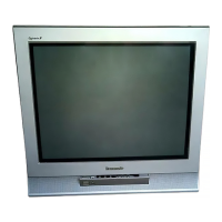
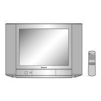
Do you have a question about the Panasonic TC-21PM50R and is the answer not in the manual?
Lists the VHF, UHF, and CATV channel ranges supported by the television receiver.
Details the specific frequency values for video and sound intermediate frequencies used in the TV.
Specifies the input and output terminal types and signal levels for audio and video signals.
Provides the high voltage specification and details about the CRT, including size and deflection.
Outlines the audio output power and speaker impedance specifications for the television.
Provides the physical dimensions (height, width, depth) and net weight of the television set.
A crucial warning for technicians regarding the dangers of servicing high-voltage electronic equipment.
Essential advice for technicians on safe practices, isolation transformers, and lead dress during servicing.
Procedures for performing cold and hot leakage current checks to prevent electrical shock hazards.
Guidelines for minimizing X-radiation exposure during TV servicing, including EHT measurement.
Illustrates the functional blocks and signal flow of the GP3 chassis television system.
Instructions on how to position the TV and remove the main board for servicing.
Step-by-step guide to access and navigate the TV's factory adjustment modes.
Procedures for adjusting the white balance of the CRT display for accurate color reproduction.
Instructions on adjusting the CRT cutoff parameters for proper black level and contrast.
Procedures for measuring and adjusting critical voltages and RF Automatic Gain Control (AGC) levels.
Steps for adjusting high voltage and NTSC system color parameters like tint and phase.
Steps for tuning PAL color signals, including local frequency and contrast settings.
How to use an oscilloscope to analyze and adjust color output waveforms for accuracy.
Steps to adjust magnetic rings for proper color purity across the screen.
Procedures for aligning the Red, Green, and Blue electron beams for sharp image convergence.
Explanations of schematic symbols, component notations, and important safety notices for diagrams.
The first part of the schematic diagram for the main A BOARD component.
The third part of the schematic diagram for the main A BOARD component.
The fourth part of the schematic diagram for the main A BOARD component.
The first part of the schematic diagram for the L BOARD component.
The second part of the schematic diagram for the L BOARD component.
Diagram showing the physical layout and identification numbers for major mechanical components.
Key to understanding abbreviations used for component types and their descriptions in the parts list.


 Loading...