EasyManua.ls Logo

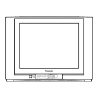
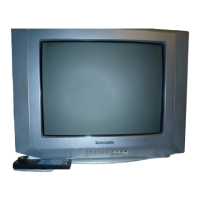
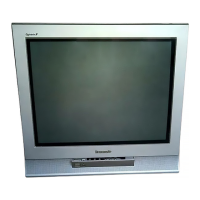
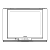
Panasonic TC-21FX30LA - User Manual

Panasonic TC-21FX30LA
49 pages
To Next Page IconTo Next Page
Loading...
TC-21FX30LA
TC-29FX30LA
TC-21FX30LP
TC-29FX30LP
Chassis GP41
Specifications are subject to change without prior notice.
Mass and dimensions shown are aproximated.
ORDER DCS - MAY2006 - 008LA - MS
Model :
Power source :
Consumption :
Antenna IN/OUT jack :
Color system :
Channel capability :
Intermediate Frequency :
Audio and Video Terminals :
Input :
Output :
High Voltage :
Picture Tube :
Audio Output :
Dimensions (HxWxD)
Weight:
TC-21FX30LA / TC-21FX30LP
127V / 220V AC Auto, 50/60Hz
67W
75Ω - VHF / UHF / CATV
PAL-M / NTSC / PAL-N
VHF: 2 ~13 - UHF: 14 ~ 69 - CATV: 1 ~ 125
Video: 45,75 MHz
Audio: 41,25 MHz
Color: PAL-M: 3,575 MHz
PAL-N:3,582 MHz
NTSC: 3,579 MHz
DVD: AV1, AV2,DVD
Y: 1,0Vp-p, 75Ω
PB: 0,7Vp-p, 75Ω
PR: 0,7Vp-p, 75Ω
Audio: 400mVrms / Video: 1,0 Vp-p 75Ω
27,5 ± 1,5 kV (at zero beam current)
PANABLACK 21", 53 cm (NBR5258) 51cm
measured diagonally
8W + 8W (RMS)
648 x 472 x 488mm
23,8 kg
TC-29FX30LA / TC-29FX30LP
127V / 220V AC Auto, 50/60Hz
98W
75Ω - VHF / UHF / CATV
PAL-M / NTSC / PAL-N
VHF: 2 ~13 - UHF: 14 ~ 69 - CATV: 1 ~ 125
Video: 45,75 MHz
Audio: 41,25 MHz
Color: PAL-M: 3,575 MHz
PAL-N:3,582 MHz
NTSC: 3,579 MHz
DVD: AV1, AV2,DVD
Y: 1,0Vp-p, 75Ω
PB: 0,7Vp-p, 75Ω
PR: 0,7Vp-p, 75Ω
Audio: 400mVrms / Video: 1,0 Vp-p 75Ω
31,0 ± 1,5 kV (at zero beam current)
PANABLACK 29", 74 cm (NBR5258) 68 cm
measured diagonally
8W + 8W (RMS)
786 x 578 x 508mm
42,7 kg
Service Manual
Specifications
© 2006 Panasonic do Brasil Limitada
CS Division
Technical Support
Question and Answer IconNeed help?

Do you have a question about the Panasonic TC-21FX30LA and is the answer not in the manual?

Panasonic TC-21FX30LA Specifications

General IconGeneral
BrandPanasonic
ModelTC-21FX30LA
CategoryTV
LanguageEnglish

Summary

Specifications

Important Safety Notice

General Guidelines

Discusses general precautions and practices for servicing electronic equipment.

Safety Precautions

Outlines critical safety measures, including handling high voltage and leakage current checks.

Lead Free Solder Information

About Lead Free Solder (PbF)

Explains the use and properties of lead-free solder and its handling precautions.

Suggested PbF Solder

Recommends specific types and sizes of lead-free solder wire for repair work.

Recognizing Lead Free Solder Usage

Provides guidance on identifying PCBs that use lead-free solder.

Chassis and Component Details

GP41 Chassis Feature Summary

Provides a summary of the key features and specifications of the GP41 chassis.

Reference Voltage

Lists key voltage measurements at specific test points for diagnosis.

Voltage Tables

Presents detailed voltage measurements for various components across different models.

System Block Diagrams

IC601 Block Diagram

Illustrates the internal functional blocks and interconnections of the main IC.

IC601 Pin Description

Details the function and type of each pin on the IC601 integrated circuit.

GP41 Chassis Block Diagram

Shows the overall block diagram of the GP41 television chassis.

Service Operations and Procedures

Service Hints

Offers practical tips and procedures for servicing the E-board.

Factory Mode Adjustment

Explains how to enter and operate the TV's service modes for adjustments.

Memory Maps Access

Describes the procedure for accessing and editing the TV's memory map data.

Colour Purity

Details the procedure for adjusting the colour purity on the CRT display.

Convergence

Outlines the steps for aligning the red, green, and blue electron beams for accurate picture display.

CRT VRS Adjustment

Describes the process for adjusting the Vertical and Horizontal Position (VRS) of the CRT display.

Television Adjustments and Calibration

Signal Alignment Adjustments

Covers RF AGC, VIF levels, PAL/NTSC signals, and protection circuit checks.

CRT Picture Quality Tuning

Includes focus, purity, sub-brightness, sub-contrast, and white balance calibration for the CRT.

Voltage and CRT Specific Settings

Covers anode/heater voltage, white quality, and CRT cut-off voltage adjustments.

Deflection Calibration and Confirmation

Deflection Calibration (Service Mode 1)

Details deflection adjustments for 50Hz operation using Service Mode 1.

Deflection Calibration (Service Mode 3)

Details deflection adjustments for 60Hz operation using Service Mode 3.

Circuit Schematics

L Board Schematic Diagram

Provides the circuit schematic for the L board of the TV.

G Board Schematic Diagram

Provides the circuit schematic for the G board of the TV.

A Board Schematic Diagram

Provides the circuit schematic for the A board of the TV.

Waveform Charts

IC601 Waveforms

Displays recorded oscilloscope waveforms for various pins of IC601.

IC451 and IC801 Waveforms

Shows oscilloscope waveforms for IC451 and IC801, aiding in troubleshooting.

Transistor Waveforms (Q501, Q551)

Displays oscilloscope waveforms for transistors Q501 and Q551.

Parts Lists

Replacement Mechanical Parts List

Lists all replaceable mechanical components with their part numbers.

Replacement Electrical Parts List (TC-21 FX30 LA; LP)

Lists all replaceable electrical components for the TC-21FX30LA/LP models.

Replacement Electrical Parts List (TC-29 FX30 LA; LP)

Lists all replaceable electrical components for the TC-29FX30LA/LP models.
Related product manuals