EasyManua.ls Logo

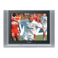
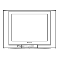
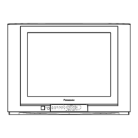
Panasonic TC-21FG10P - User Manual

Panasonic TC-21FG10P
28 pages
To Next Page IconTo Next Page
Loading...
Power Source : AC AUTO 110-240V, 50/60 Hz
Power Consumption : 83W
Aerial Impedance : 75 unbalanced
Coaxial type
Receiving Channels :
VHF 2-13 (USA STANDARD)
CATV 1-125 (USA STANDARD)
UHF 14-69 (USA STANDARD)
Intermediate Frequency :
Video 38.0 MHz
Sound 31.5 MHz (D, K, K1)
32 MHz (I)
32.5 MHz (B, G)
33.5 MHz (M)
Colour 33.57 MHz (PAL)
33.6 MHz (SECAM)
33.75 MHz (SECAM)
34.42 MHz (NTSC)
© 2005 Matsushita Electric Industrial Co., Ltd. All
rights reserved. Unauthorized copying and
distribution is a violation of law.
TC-21FG10P
GP31 Chassis
Video / Terminals : AV1, 2
RAV In Video In 1 Vp-p 75
Audio In Approx. 400mVrms
Monitor Out Video Out 1 Vp-p 75
Audio Out Approx. 400mVrms
High Voltage :
27.5kV±1.5
at zero beam current
Picture Tube : A51LXR195X
51cm (21 inches)
Measured diagonally,
90° deflection
Audio Output : 16.0W
Dimensions : Height:473mm
Width : 648 mm
Depth : 488 mm
Mass : 24 kg (Net Wt.)
Specifications are subject to change without notice.
Mass and dimensions shown are approximate.
Colour Television
Specifications
ORDER NO. MTV0501395C3
Question and Answer IconNeed help?

Do you have a question about the Panasonic TC-21FG10P and is the answer not in the manual?

Panasonic TC-21FG10P Specifications

General IconGeneral
BrandPanasonic
ModelTC-21FG10P
CategoryTV
LanguageEnglish

Summary

Safety Precautions

General Guide Lines

General safety guidelines and precautions for servicing the unit.

Leakage Current Cold Check

Procedure for performing a cold leakage current check.

Leakage Current Hot Check

Procedure for performing a hot leakage current check.

X-Radiation

Information and precautions regarding X-Radiation hazards.

GP31 Chassis Block Diagram

Block diagram illustrating the GP31 chassis components and connections.

Service Hints

Service Position for E-Board

Instructions on how to position the E-Board for servicing.

Factory Mode Adjustment

Steps to enter and perform factory mode adjustments.

Adjustment for White Balance

Procedure for adjusting the white balance of the picture.

Adjustment for CRT CUT OFF

Procedure for adjusting the CRT CUT OFF.

Adjustment Procedure

Detailed procedures for various critical adjustments including voltage, AGC, and colour.

PAL Colour

Procedure for adjusting PAL colour signals.

Adjustment

General adjustment steps, likely for picture or colour parameters.

Colour Purity

Procedure for adjusting colour purity on the CRT screen.

Convergence

Procedure for adjusting screen convergence for picture alignment.

Adjustment of CRT VRS

Procedure for adjusting CRT Vertical and Horizontal alignment (VRS).

Conductor Views

Schematic Diagram

A Board (1;5)

Schematic diagram for A Board, part 1 of 5.

A Board (2;5)

Schematic diagram for A Board, part 2 of 5.

A Board (3;5)

Schematic diagram for A Board, part 3 of 5.

A Board (4;5)

Schematic diagram for A Board, part 4 of 5.

A Board (5;5)

Schematic diagram for A Board, part 5 of 5.

L Board (1;3)

Schematic diagram for L Board, part 1 of 3.

L Board (2;3)

Schematic diagram for L Board, part 2 of 3.

L Board (3;3)

Schematic diagram for L Board, part 3 of 3.

Parts Locations

Replacement Parts List

Replacement Parts List

Comprehensive list of replacement parts with part numbers and descriptions.
Related product manuals