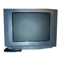
Do you have a question about the Panasonic TC-21Z99R and is the answer not in the manual?
General guidelines for servicing, emphasizing isolation transformers, high voltage precautions, and protective devices.
Procedure to check leakage current with the unit unplugged using an ohmmeter and jumpered plug.
Procedure to measure leakage current with the unit plugged in, using a resistor and AC/DC meter for shock hazard prevention.
Addresses X-radiation sources and precautions, including EHT measurement and picture tube replacement.
Details the correct procedure for accessing and orienting the TV for servicing the E-Board.
Instructions for entering factory mode and navigating adjustment checks (CHK1-CHK4) using remote control commands.
Procedure to confirm +B DC voltage at specific test points after setting brightness and contrast to minimum.
Method to confirm heater voltage using a high-frequency voltmeter after displaying a crosshatch pattern.
Steps to adjust RF AGC using remote control and checking signal strength impact on tuner voltage.
Procedure for adjusting NTSC Sub-Tint using an oscilloscope, verifying colour level and phase.
Procedure for adjusting PAL colour output levels (G OUT, R OUT) using an oscilloscope and specific test points.
Guide to adjusting CRT VRS by manipulating magnets and observing cross hatch pattern for alignment.
Method for adjusting CRT Cut Off using an oscilloscope to achieve a 1-H line display.
Process for adjusting colour purity and convergence, involving degaussing and deflection yoke positioning.
Procedure for white balance adjustment in Low Light and High Light conditions using a colour analyzer.
Guidance on measurement, signal flow, and safety precautions relevant to schematic diagrams.
First part of the A Board schematic, showing component layout and initial circuit sections.
Second part of the A Board schematic, detailing integrated circuits and signal path connections.
Third part of the A Board schematic, illustrating audio circuits and specific chip connections.
Fourth part of the A Board schematic, covering tuner and IF sections with terminal interfaces.
Final part of the A Board schematic, showing AV inputs, monitor outputs, and connectors.
First part of the L Board schematic, detailing signal inputs and basic component configurations.
Second part of the L Board schematic, focusing on the CRT circuit and deflection components.
Final part of the L Board schematic, showing connections to the CRT and high-voltage components.
Detailed list of all replaceable parts with reference numbers, part numbers, descriptions, and remarks.




 Loading...