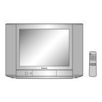
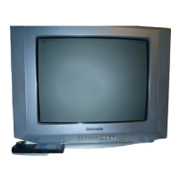
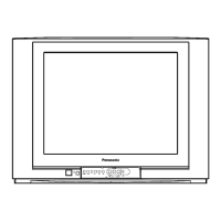
Do you have a question about the Panasonic TC-21GF10R and is the answer not in the manual?
Block diagram illustrating the functionality and connections of the TA 8859P integrated circuit.
Block diagram showing the AN5071 integrated circuit's internal structure and external connections.
Diagram detailing the UPC2801AHA IC, including its input/output pins and functions.
Schematic representation of the AN5607K integrated circuit and its signal flow.
Oscilloscope display of the composite video signal at IC101 Pin 11.
Waveforms for Y, Chroma, B-Y, R-Y signals at IC601 pins.
Waveforms for horizontal output signals from IC601 Pin 19 and Q501.
Oscilloscope traces for vertical output signals at IC601 Pin 9 and IC451 Pin 2.
Waveforms at high-voltage points like FBT Pin 4, FBT Pin 6, and Q501 Collector.
Table listing measured voltages at various test points across different ICs.
Schematic illustration of the EUR641952 remote control's internal circuitry.
Table mapping remote control buttons to their respective functions and data codes.
Schematic diagram of the power supply board, detailing components and layout.
Diagrams showing the power supply's hot and cold circuit divisions and components.
Schematic details of power supply ICs (IC802, IC803, IC804) and associated parts.
Circuit diagram for the remote control receiver IC (UPC2801AHA) and board.
Schematic detailing AV1 and AV2 input connections and monitor output ports.
Diagram of the AR1 connector pin assignments for AV and monitor signals.
Detailed schematic showing connections to the Cathode Ray Tube (CRT).
Schematic of circuits responsible for driving and biasing the CRT.

