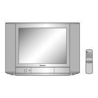
Do you have a question about the Panasonic TC-21GX30P and is the answer not in the manual?
Advises on using an isolation transformer, lead dress, protective devices, and unplugging for long periods.
Instructs to unplug the AC cord and check resistance between the plug and exposed metallic parts.
Details measuring leakage current with a resistor and AC/DC meter when the TV is powered on.
Warns about X-radiation from EHT and picture tube, stressing use of proper test jigs and meters.
Provides instructions on how to position the TV and remove the main board for servicing.
Explains how to enter service mode and navigate through adjustment options (CHK1).
Specifies adjustment targets for Sub Bright, R-CUT OFF, and G-CUT OFF in low light conditions.
Specifies adjustment targets for Sub Bright, R-Drive, and G-Drive in high light conditions.
Details the preparation and procedure for adjusting the +B voltage, including test points and expected values.
Outlines the preparation and steps for adjusting high voltage, including crosshatch pattern and screen VR.
Step-by-step guide for adjusting colour purity, including degaussing and deflection yoke positioning.
Instructions for adjusting static and dynamic convergence using magnets and deflection yoke.
Schematic diagram for the A Board, section 1 of 5, showing component layout and connections.
Schematic diagram for the A Board, section 2 of 5, detailing electronic components and their interconnections.
Schematic diagram for the A Board, section 3 of 5, illustrating circuit details and component placement.
Schematic diagram for the A Board, section 4 of 5, showing specific circuit segments and part numbers.
Schematic diagram for the A Board, section 5 of 5, concluding the board's circuit representation.
Schematic diagram for the L Board, section 1 of 3, detailing the CRT circuit and connections.
Schematic diagram for the L Board, section 2 of 3, focusing on IC351 and associated components.
Schematic diagram for the L Board, section 3 of 3, showing CRT connections and test points.
Provides abbreviations and examples for resistor part naming conventions and allowances.
Explains abbreviations and examples for capacitor part naming conventions and allowances.


 Loading...