EasyManua.ls Logo

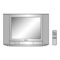
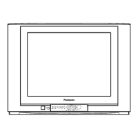
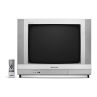
Panasonic TC-29FX20R User Manual

Panasonic TC-29FX20R
30 pages
To Next Page IconTo Next Page
Page #1 background imageLoading...
Page #1 background image
Power Source : AC AUTO 110-240V, 50/60 Hz
Power Consumption : 98W
Aerial Impedance : 75 unbalanced
Coaxial type
Receiving System :
17 Systems
Receiving Channels :
VHF 2-12 PAL / SECAM B,K1
0-12 PAL B (AUST)
1-9 PAL B (N.Z)
1-12 PAL/SECAM D
1-12 NTSC M (JAPAN)
2-13 NTSC M (U.S.A)
UHF 21-69 PAL G,H,I / SECAM G,K,K1
28-69 PAL B (AUST)
13-57 PAL D,K
13-62 NTSC M (JAPAN)
13-69 NTSC M (USA)
CATV S1-S20 (OSCAR)
1-125 (U.S.A CATV)
C13-C49 (JAPAN)
S21-S41 (HYPER)
Z1-Z37 (CHINA)
5A, 9A (AUST)
Video / Audio Terminals :
DVD
Y 1.0Vp-p, 75
PB 0.7Vp-p, 75
© 2006 Matsushita Electric Industrial Co., Ltd. All
rights reserved. Unauthorized copying and
distribution is a violation of law.
TC-29FX20R
GP41 Chassis
PR 0.7Vp-p, 75
AV 1,2,3
Video In 1Vp-p, 75
Audio In Approx. 0.5V, 47k
Monitor Out
Video Out 1Vp-p, 75
Audio Out Approx. 0.5V, 1k
Intermediate Frequency :
Video 38.0 MHz
Sound 31.5 MHz (D, K, K1)
32 MHz (I)
32.5 MHz (B, G)
33.5 MHz (M)
Colour 33.57 MHz (PAL)
33.6 MHz (SECAM)
33.75 MHz (SECAM)
34.42 MHz (NTSC)
High Voltage : 31.0kV ±1.0
at zero beam current
Picture Tube : A68LZU185X-E
67.6cm (29 inches)
Measured diagonally,
90° deflection
Audio Output : 16.0W
Dimensions : Height:578mm
Width : 786 mm
Colour Television
Specifications
ORDER NO. MTV0601431CE
Question and Answer IconNeed help?

Do you have a question about the Panasonic TC-29FX20R and is the answer not in the manual?

Panasonic TC-29FX20R Specifications

General IconGeneral
BrandPanasonic
ModelTC-29FX20R
CategoryTV
LanguageEnglish

Summary

Safety Precautions

General Guide Lines

Essential safety rules for servicing the television set.

Leakage Current Cold Check

Procedure for checking electrical leakage with the receiver unplugged.

Leakage Current Hot Check

Procedure for checking electrical leakage with the receiver powered on.

X-Radiation

Safety measures to prevent X-radiation exposure during service.

GP41 Chassis Block Diagram

Visual representation of the GP41 chassis functional components and connections.

Service Hints

Service Position for E-Board

Recommended physical orientation for accessing the E-Board during service.

Adjustment for White Balance

Procedure for calibrating the TV's color accuracy and display.

Adjustment for CRT CUT OFF

Method for setting the CRT cut-off voltages for proper picture display.

Adjustment Procedure

Steps for performing key voltage and high voltage adjustments.

Adjustment

Procedures for color purity and convergence adjustments.

Conductor Views

Schematic Diagram

A Board

Detailed schematic for the A Board, a main circuit board.

L Board

Detailed schematic for the L Board, related to CRT circuitry.

G Board

Detailed schematic for the G Board, likely for general functions.

Parts Locations

Replacement Parts List

Replacement Parts List

Comprehensive list of part numbers and descriptions for replacement.

Related product manuals