EasyManua.ls Logo

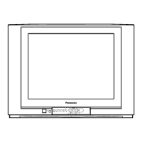
Panasonic TC-29PS70R User Manual

Panasonic TC-29PS70R
42 pages
To Next Page IconTo Next Page
Page #1 background imageLoading...
Page #1 background image
Power Source AC Auto 110-240 V, 50/60 Hz
Power Consumption 148 W
Standby condition : 2 W
Aerial Terminal Impedance : 75, Coaxial type
Tuning System Frequency Synthesizer
Auto Search Tuning
Pos : 100 Positions
Receiving System 17 Systems
Receiving Channels Regular TV
VHF BAND 2-12 (PAL/SECAM B, K1)
0-12 (PAL B AUST.)
1-9 (PAL B N.Z.)
1-12 (PAL/SECAM D)
1-12 (NTSC M Japan)
2-13 (NTSC M U.S.A)
UHF BAND 21-69 (PAL G, H, I/SECAM G, K, K1)
28-69 (PAL B AUST.)
13-57 (PAL D, K)
13-62 (NTSC M Japan)
14-69 (NTSC M U.S.A.)
CATV S1-S20 (OSCAR)
1-125 (U.S.A. CATV)
C13-C49 (JAPAN)
S21-S41 (HYPER)
Z1-Z37 (CHINA)
Intermediate Frequency 38.0 MHz
© 2002 Matsushita Electric Industrial Co., Ltd. All
rights reserved. Unauthorized copying and
distribution is a violation of law.
TC-29PS70R
MX-12 Chassis
Video 31.5 MHz (D, K) / 32.5 MHz (B, G)
32.0 MHz (I) / 32.5 MHz (M)
Sound 33.57 MHz (PAL) /
Colour 33.6 MHz (SECAM)
34.42 MHz (NTSC) /
33.75 MHz (SECAM)
Receiving Stereo Sound System AV STEREO
Video/Audio/Terminals IN S-Video Y:1.0Vp-p 75
AV 1, 2, 3, 4 DVD IN S-Video C:0.3Vp-p 75
Y/P
B
/P
R
(Phone Type) Y:1.0Vp-p 75 PB,
PR:0.7Vp-p 75 Video 1.0Vp-p
75 Audio Approx. 400mV 47K
Video 1.0Vp-p 75
Monitor Out Audio Approx. 400mV 47K
High Voltage 31.0 (+0.7, -1.5kV) at zero
beam current
Picture Tube M68LQK186XH Type 29 (68 cm)
Measured diagonally,
104° deflection
Audio Output 20 W speaker
Dimensions (W x D x H) 820 mm x 495.9 mm x 563.7 mm
Weight (Mass) 48 kg (Net)
Note:
Specifications are subject to change without notice. Mass and
dimensions shown are approximate.
Colour Television
Specification
Order No. MTV0207202C3
Question and Answer IconNeed help?

Do you have a question about the Panasonic TC-29PS70R and is the answer not in the manual?

Panasonic TC-29PS70R Specifications

General IconGeneral
Screen Size29 inches
Display TypeCRT
Aspect Ratio4:3
Weight40 kg
Input/Output ConnectorsComposite, S-Video, RF
Input PortsComposite, S-Video, RF

Summary

Safety Precautions

General Servicing Guide

General advice for servicing, including safety transformer use and discharging anode.

Leakage Current Checks

Procedures for checking AC cord leakage current, both cold and hot.

X-Radiation Safety and Block Diagram

Precautions regarding X-radiation and overview of the TV's block diagram.

Control and Circuit Board Locations

Rear Panel Controls

Identifies external controls and connectors on the TV's rear panel.

Circuit Board Identification

Maps circuit board names to their physical locations and functions.

Service Hints and Chassis Access

Moving Chassis for Service

Step-by-step guide on how to safely access the TV chassis for servicing.

Market Mode Functionality

Market Mode and CHK Mode Operation

Instructions for entering and navigating TV's market mode and check modes.

Adjustment Procedures

Voltage, AGC, and Output Adjustments

Procedures for adjusting B voltage, RF AGC, colour output, and high voltage.

Colour, Tint, Purity, and Convergence

Adjustments for sub tint, sub contrast, colour purity, and convergence.

White Balance Adjustment

Steps to adjust white balance by setting RGB CUT OFF and DRIVE levels.

Conductor Views

A-Board Component Layout

Visual guide showing the component placement on the A-Board.

Schematic Diagrams

TC-29PS70R (MX-12 Chassis) Schematic Overview

Detailed circuit diagrams for the TV model, including component notations.

A Board Schematics

Detailed circuit diagrams and component layout for the A Board (pages 15-18).

GM Board Schematics

Detailed circuit diagrams and component layout for the GM Board (pages 19-20).

H Board Schematics

Detailed circuit diagrams and component layout for the H Board (pages 21-22).

YC Board Schematics

Detailed circuit diagrams and component layout for the YC Board (pages 23-24).

L Board Schematics

Detailed circuit diagrams and component layout for the L Board (pages 25-26).

K Board Schematics

Detailed circuit diagrams and component layout for the K Board (pages 27-28).

X Board Schematics

Detailed circuit diagrams and component layout for the X Board (pages 29-30).

Parts Locations Diagram

Replacement Parts List

Parts List Notes and Abbreviations

Explains abbreviations, part naming conventions, and safety notices for the parts list.

Main Replacement Parts List

Comprehensive list of part numbers, descriptions, and references for TV components.

Related product manuals