- 11 -
TC-20KL03A / TC-29KL03A
ADJUSTMENTS
ITEM / PREPARATION PROCEDURE
8- MTS CALIBRATION
STEREO SEPARATING ADJUSTMENT
1. Connect the oscilloscope in TPA42.
2. Connect the RF generator in the tuner terminal.
3. Adjust AVL to ON.
ADJUSTMENT:
1. Select stereo mode in the audio menu.
2. Supply the signal through RF antenna input:
VIDEO: 100 IRE FLAT FIELD, 30% of modulation
AUDIO: 300 Hz, 30% of modulation, stereo (left only)
(70 ± 5 dB, open, 75W, P/S 10dB)
3.Adjust LB SEPARATION (CHK5) so that the sign
visualized in the oscilloscope is minimum.
4. Supply the signal through RF antenna input:
VIDEO: 100 IRE FLAT FIELD, 30% of modulation
AUDIO: 3 kHz, 30% of modulation, stereo (left only) (70
± 5 dB, open, 75W, P/S 10dB)
5. Adjust HB SEPARATION (CHK5) so that the sign
visualized in the oscilloscope is minimum
6. Repeat the steps 2 to 5.
9- PROTECTION CIRCUIT (SHUTDOWN)
OPERATION
1. Supply a CROSS-HATCH signal.
2. Adjust CONTRAST and BRIGHT controls to minimum.
CONFIRMATION:
1. Connect the voLtmeter in TPA22 and confirm that the
voltage is smaller than [A].
2. Connect a DC source in TPA22 and confirm that the
protection circuit doesn't act when the voltage is [B].
3. Confirm that the protection circuit acts with smaller
voltage than [C].
Condition / CRT 20 pol 29 pol
[A] 22,03V 24,12V
[B] 23,02V 24,50V
[C] 25,52V 27,56V
4
1 2 3
3 2 1
Fig. 2
10- FOCUS CALIBRATION
• Assure that the SUB-BRIGHTNESS adjustment has been
done.
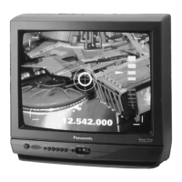
1. Supply a Philips or monoscope pattern signal.
2. Adjust MENU OF IMAGE to DYNAMIC NORMAL.
CALIBRATION:
1. Adjust the FOCUS variable resistor for the point of
better adjustment.
with PHILIPS signal .... take as reference for
adjustment the third vertical line (fig. 1).
with MONOSCOPE signal in the number 4 (fig.2).
Fig. 1
 Loading...