EasyManua.ls Logo

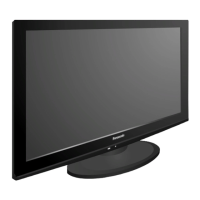
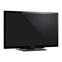
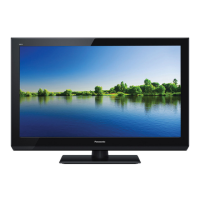
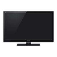
Panasonic TC-L37E3L

Panasonic TC-L37E3L
8 pages
To Next Page IconTo Next Page
Loading...
© Panasonic Corporation 2011.
Unauthorized copying and distribution is a violation
of law.
ORDER NO.MTNC110664AE
37 inch Class 1080p LCD HDTV
Model No. TC-L37E3L
LA15 Chassis
TABLE OF CONTENTS
PAGE PAGE
1 Different points---------------------------------------------------- 2
1.1. Mechanical Replacement Parts List ------------------ 2
1.2. Electrical Replacement Parts List --------------------- 2
2 Schematic Diagram ---------------------------------------------- 3
2.1. A-Board (1/9) Schematic Diagram -------------------- 3
2.2. A-Board (4/9) Schematic Diagram -------------------- 4
2.3. A-Board (6/9) and KA-Board Schematic
Diagram ------------------------------------------------------ 5
2.4. A-Board (7/9) Schematic Diagram -------------------- 6
2.5. A-Board (8/9) Schematic Diagram -------------------- 7
2.6. LD-Board Schematic Diagram ------------------------- 8
Please file and use this manual together with the service manual for Model No.
TC-L37E3, ORDER NO. MTNC110209CE.
Question and Answer IconNeed help?

Do you have a question about the Panasonic TC-L37E3L and is the answer not in the manual?

Panasonic TC-L37E3L Specifications

General IconGeneral
BrandPanasonic
ModelTC-L37E3L
CategoryLCD TV
LanguageEnglish

Summary

Different points

Mechanical Replacement Parts List

Lists mechanical replacement parts with part numbers, descriptions, and quantities.

Electrical Replacement Parts List

Details electrical replacement parts, including PCBs, ICs, capacitors, resistors, and connectors.

Schematic Diagram

A-Board (19) Schematic Diagram

Provides the first part of the A-Board schematic, detailing its circuit connections and components.

A-Board (49) Schematic Diagram

Presents the fourth section of the A-Board schematic, illustrating specific circuit blocks and links.

A-Board (69) and KA-Board Schematic Diagram

Includes schematics for A-Board (6/9) and KA-Board, showing their integrated circuit layouts.

A-Board (79) Schematic Diagram

Details the seventh segment of the A-Board schematic, covering particular circuit functions.

A-Board (89) Schematic Diagram

Offers the eighth part of the A-Board schematic, mapping out its overall circuit design.

LD-Board Schematic Diagram

Illustrates the LD-Board schematic, focusing on the LED driver circuitry and connections.
Related product manuals