29
9 Measurements and Adjustments
9.1. Voltage chart of A-board
9.2. Picture level adjustment (RF)
VOLTAGE TEST POINT SPECIFICATION
(Reception state)
REMARKS
SUB1.2V TP8100 1.2 - 1.31 V
SUB1.5V TP8101 1.47 - 1.55 V
SUB3.3V TP5400 3.17 - 3.43 V
SUB5V TP5420 4.94 - 5.31 V
USB5V TP5440 4.94 - 5.31 V
PNL12V TP4089 or TP4041 or
TP4092 or TP4095
11.5 - 12.5 V
Instrument Name Remarks
1. REMOTE TRANSMITTER
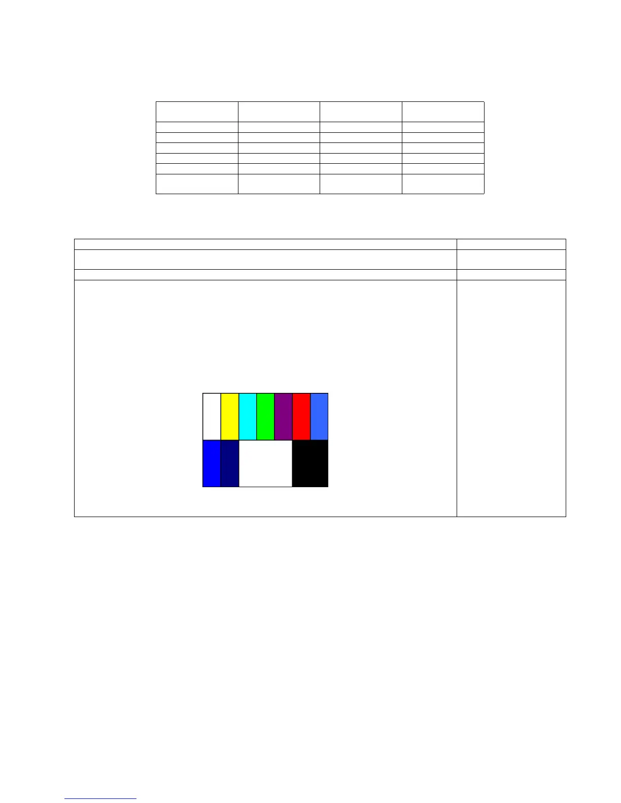
2. Ex. Signal (Sprit color bar)
Adjustment or Inspection Procedure Remarks
< procedure >
1. Receive the Sprit color bar.
(Screen mode: ZOOM or FULL Picture mode: DYNAMIC AI: OFF AI Picture: OFF)
*BACK LIGHT +30
< Inspection >
1. Enter Service mode, and select MAIN_ADJ PICTURE.
Volume UP/DOWN key makes GAIN displayed under PICTURE to set.
Pushing the remote controller [OK] key for about 3 seconds, GAIN is suited
to the adjustment value automatically.
(The Sprit Color Bar Pattern)
 Loading...