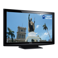
Slide 59
Power On Operation (3D Model TC-P50VT20)
The power command from the power switch on the A board or the remote control
receiver on the K board is provided to the CPU (IC1100) in the A board.
The CPU on the A board outputs 2 commands:
1. The “TV_SUB_ON” command.
2. The “PANEL_STB_ON” command.
The “TV_SUB_ON” (3.2V) command is provided to the power supply on pin 5 of
connector P7. The power supply outputs F15V to the A board when it receives this
command.
The F15V from pins 6~8 of connector P6 on the P board is applied to pins 6~8 of
connector A6 in the A board. This voltage is applied to a regulator circuit that
generates: SUB1.2V, SUB1.5V, SUB3.3V, SUB5V, and SUB9V. These SUB-Voltages
are used for signal processing.
The “PANEL_STB_ON” (3.2V) is output from the Main CPU (IC1100) after it has
confirmed the presence of all the SUB voltages.
This command is used to turn on circuits in the both the A board and the D board.
• In the A board, it is responsible for generating the voltages used by the MIHO-3D
(IC5800) and the 3D Eyewear Driver/Transmitter circuit.
• In the D board, it’s used to turn on the 3.3V regulator (IC9400).
 Loading...