Do you have a question about the Panasonic TX-32LE7P/SA and is the answer not in the manual?
General guidelines for servicing procedures and safety.
Procedure and limits for checking touch currents for shock prevention.
Recommendations for types of lead-free solder for repair work.
Step-by-step guide to detach the TV pedestal assembly.
Instructions for removing the television's back cover.
Identification and layout of the main circuit boards within the chassis.
Guide to identifying and tracing specific wire connections in the unit.
Table detailing test points and expected voltage values for verification.
Steps to access the service mode for TV adjustments.
Explanation of remote control buttons used for service adjustments.
Procedure and required instruments for white balance calibration.
Critical safety components and replacement part requirements.
Information on component availability after product discontinuation.
Specific variations for the TX-26LE7FA model.
Specific variations for the TX-26LE7PA model.
Specific variations for the TX-26LE7LA model.
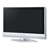
Specific variations for the TX-32LE7F/SA model.
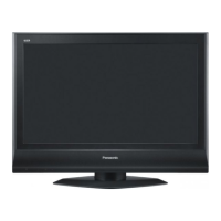
Specific variations for the TX-32LE7P/SA model.
Specific variations for the TX-32LE7LA model.
Specific variations for the TX-32LE7PA model.
Specific variations for the TX-R32LE7A model.
Specific variations for the TX-R26LE7A model.
Critical safety notes for working with schematic diagrams.
Explanations of symbols, units, and conventions used in schematics.
Part 1 of the A-Board schematic diagram.
Part 2 of the A-Board schematic diagram.
Part 3 of the A-Board schematic diagram.
Part 4 of the A-Board schematic diagram.
Part 5 of the A-Board schematic diagram.
Schematic diagram for the B-Board.
Schematic diagram for the H-Board.
Schematic diagram for the P-Board.
Schematic diagram for the K-Board.
Schematic diagram for the V-Board.
Top view conductor layout for the A-Board.
Conductor layout for the P-Board.
Conductor layouts for V-Board and B-Board.
| Screen Size | 32 inches |
|---|---|
| Display Type | LCD |
| Backlight Type | CCFL |
| Aspect Ratio | 16:9 |
| Brightness | 500 cd/m² |
| Response Time | 8 ms |
| Viewing Angle | 178° |
| Sound Output | 20W |
| VGA Port | 1 |
| Resolution | 1366 x 768 |
| Audio Output | 2 x 10W |