EasyManua.ls Logo

Panasonic TX-32LE8P

Panasonic TX-32LE8P
39 pages
To Next Page IconTo Next Page
Loading...
Service Manual
Colour LCD Television
TX-32LE8F
TX-32LE8FS
TX-32LE8L
TX-32LE8P
TX-32LE8PS
GLP23A Chassis
Specifications
Power Source: 220-240V AC, 50Hz
Power Consumption 121W
Stand-by Power Consumption: 1W
Aerial Impedance: 75Ω unbalanced, Coaxial Type
Receiving System: PAL-I/H, B/G, D/K,
SECAM B/G, D/K, L/L’
PAL-525/60 (AV only)
M.NTSC (AV only)
NTSC (AV only)
Receiving Channels: VHF E2-E12 VHF H1-H2 (ITALY)
VHF A-H (ITALY) VHF R1-R2
VHF R3-R5 VHF R6-R12
UHF E21-E69 CATV (S01-S05)
CATV S1-S10 (M1-M10) CATV S11-S20 (U1-U10)
CATV S21-S41 (Hyperband)
Operating Conditions: Temperature: 0°C ÷ 35°C
Humidity: 20% ÷ 80% RH (non condensing)
Scanning format: 480i(60Hz), 480p(60Hz), 576i(50Hz), 576p(50Hz), 720p(60Hz), 720p(50Hz), 1.080i(60Hz),
1.080i(50Hz),
Intermediate Frequency:
Video/Audio
Video 38,9MHz, 33,9MHz
Audio 33,4MHz (B/G), 33,16MHz (A2)
33,05MHz (NICAM B/G, D/K, L)
32,4MHz (D/K), 32,66MHz (CZ STEREO)
40,4MHz (L
), 39,75MHz (LNICAM)
Colour 34,47MHz (PAL)
34,5MHz, 34,65MHz (SECAM)
38,3MHz, 38,15MHz (SECAM L
)
ORDER No. PCZ0805037CE
All manuals and user guides at all-guides.com
all-guides.com
Question and Answer IconNeed help?

Do you have a question about the Panasonic TX-32LE8P and is the answer not in the manual?

Panasonic TX-32LE8P Specifications

General IconGeneral
Screen Size32 inches
Display TechnologyLCD
USB Ports1
Aspect Ratio16:9
VGA InputYes
Resolution1366 x 768
Sound Output20W

Summary

Specifications

Power Source and Consumption

Details on the TV's power requirements and energy usage.

Receiving System and Channels

Information on TV broadcast standards and channel tuning capabilities.

Terminals and Connectors

Description of input/output ports for AV, HDMI, and other signals.

LCD Screen and Audio Specs

Technical details of the LCD panel and audio output capabilities.

Dimensions and Weight

Physical measurements and weight of the TV set with and without stand.

Safety Precautions

General Service Guidelines

Basic rules and recommendations for performing service safely.

Touch-Current Safety Check

Procedure for measuring touch currents to prevent electrical hazards.

Electrostatic Discharge (ESD) Prevention

Methods to protect sensitive electronic components from static electricity damage.

Lead Free Solder Information

About Lead Free Solder (PbF)

Explanation of lead-free solder composition and its use in manufacturing.

Applicable Signals

Component and HDMI Signal Compatibility

List of compatible video signal formats for Component and HDMI inputs.

Service Procedures

Backcover and Pedestal Removal

Step-by-step instructions for disassembling the TV's outer casing.

Setting Inspection and Voltage Confirmation

Procedures for checking operational voltages and settings.

Self-Check Functionality

Guide to using the TV's built-in diagnostic self-check mode.

Adjustment Method and Key Commands

Instructions for entering service mode and using remote control commands.

White Balance Adjustment Procedure

Steps for calibrating the TV's color balance using specialized equipment.

System Diagrams

Wiring Diagram

Schematic showing interconnections between major circuit boards and components.

Video & Stereo Audio Block Diagram

Block diagram illustrating the signal flow for video and audio processing.

Power Supply Block Diagram

Diagram showing the power distribution and regulation within the TV.

Control Block Diagram

Block diagram detailing the control signals and logic flow.

Parts Location

Exploded View Overview

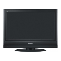
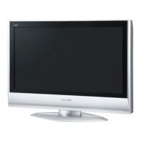
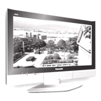
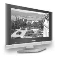
Visual guide showing the physical arrangement of major external parts.

Accessory Identification

Identification of included accessories like remote control and cables.

Replacement Parts List

Common Parts and Exploded View

List of common components and parts referenced in the exploded view.

Miscellaneous Components

Catalog of various non-specific electronic components and hardware.

Resistor and Diode List

Detailed listing of resistors and diodes with their respective part numbers.

Schematic Diagrams

Schematic Diagram Notes and Symbols

Explanation of symbols, notes, and measurement conventions used in schematics.

A-BOARD Schematic Diagram

Circuit diagram for the main A-BOARD (1 of 5).

G-BOARD Schematic Diagram

Circuit diagram for the G-BOARD.

V-BOARD Schematic Diagram

Circuit diagram for the V-BOARD.

K-BOARD Schematic Diagram

Circuit diagram for the K-BOARD.

Conductor Views

A-BOARD Top View and Layout

Top-side view of the A-BOARD showing component placement and traces.

A-BOARD Bottom View and Layout

Bottom-side view of the A-BOARD showing component placement and traces.

V-BOARD Top View and Layout

Top-side view of the V-BOARD showing component placement and traces.

Related product manuals