EasyManua.ls Logo

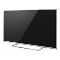
Panasonic TX-42A400B

Panasonic TX-42A400B
66 pages
To Next Page IconTo Next Page
Loading...
Service Manual
LCD Television
TX-42A400B
KM25E Chassis
© Panasonic Corporation 2014.
Unauthorized copying
and
distribution is a violation of law.
ORDER No. PCZ1403045CE
There are special components used in this equipment which are important for safety. These parts are marked in the
Schematic Diagrams, Circuit Board Diagrams, Explorer Views and Replacement Parts List. It is essential that these
critical parts should be replaced with manufacturer´s specified parts to prevent shock, fire or other hazards. Do not
modify the original design without permission of manufacturer.
IMPORTANT SAFETY NOTICE
This service information is designed for experienced repair technicians only and is not designed for use by the general public. It does not
contain warnings or cautions to advise non-technical individuals of potencial dangers in attempting to service a product. Products
powered by electricity should be serviced or repaired only by experienced professional technicians. Any attempt to service or repair the
product or products deal within this service information by anyone else could result in serious injury or death.
Warning
Question and Answer IconNeed help?

Do you have a question about the Panasonic TX-42A400B and is the answer not in the manual?

Panasonic TX-42A400B Specifications

General IconGeneral
Screen Size42 inches
Resolution1920 x 1080
Display TypeLCD
Backlight TechnologyLED
HDMI Ports2
USB Ports1
Weight9.5 kg
Refresh Rate50 Hz
Sound Output20 W

Summary

Safety Precautions

General Guide Lines

Guidelines for safe servicing and handling of equipment.

Touch-Current Check

Procedure for measuring touch current to ensure safety.

Prevention of Electrostatic Discharge (ESD)

ESD Handling Techniques

Methods to reduce component damage from static discharge.

About Lead Free Solder (PbF)

Service Navigation

Chassis Board Layout

Visual identification and function of major circuit boards in the chassis.

Service Hints

How to Remove the Backcover

Step-by-step instructions for disassembling the TV's back cover.

Applicable Signals

Specifications

Technical Description

Model and Keys

Details on model compatibility with CI PLUS and HDCP.

Setting Inspection

Voltage Confirmation

Expected voltage values at various test points on A and P boards.

Service Mode Function

Service Mode Access and Operations

Procedures for entering, exiting, and operating the service mode menu.

Hotel Mode

Hotel Mode Setup and Functions

Configuration options and purpose of the hotel mode feature.

Self Check

Self-Check Procedure

Steps to access and perform self-checks for system diagnostics.

Power LED Blinking Timing Chart

Adjustment Method

White Balance Adjustment

Procedure and parameters for adjusting white balance using specific equipment.

Wiring Diagram

Block Diagram

Parts Location

Location of Lead Wiring

Replacement Parts List Note

Parts List

Schematic Diagrams Note

Schematic Symbols and Remarks

Explanation of symbols, notes, and safety remarks for schematic diagrams.

A-BOARD Schematics

P-BOARD Schematics

LD-BOARD Schematics

K-BOARD Schematics

GK-BOARD Schematics

Conductor Views

A-BOARD - TOP

Top-side component layout and routing for the A-BOARD.

A-BOARD - BOTTOM

Bottom-side component layout and routing for the A-BOARD.

P-BOARD - TOP

Top-side component layout and routing for the P-BOARD.

P-BOARD - BOTTOM

Bottom-side component layout and routing for the P-BOARD.

LD-BOARD - TOP

Top-side component layout and routing for the LD-BOARD.

LD-BOARD - BOTTOM

Bottom-side component layout and routing for the LD-BOARD.

GK-BOARD - TOP

Top-side component layout and routing for the GK-BOARD.

GK-BOARD - BOTTOM

Bottom-side component layout and routing for the GK-BOARD.

K-BOARD Conductor Views

Component layout for the K-BOARD.

Related product manuals