29
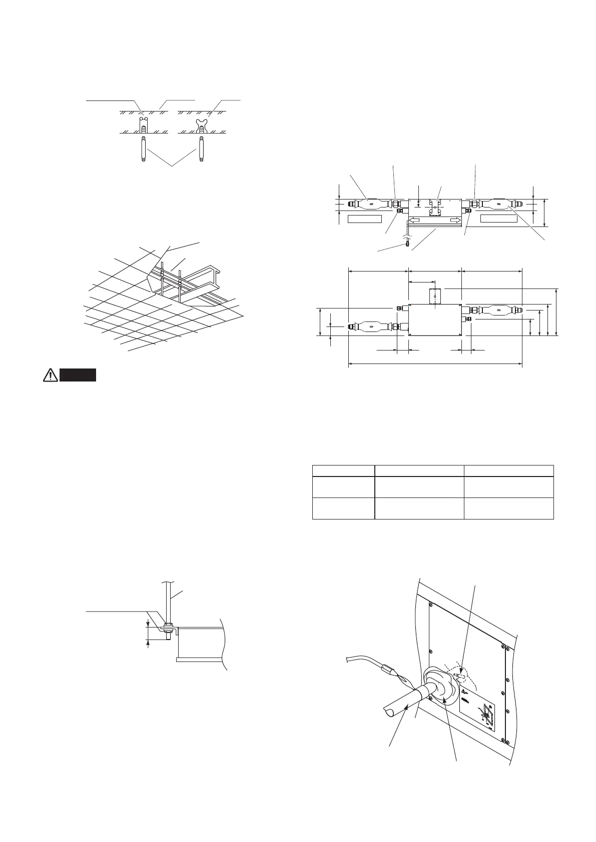
Hole-in-anchor
Hole-in-plug
Concrete
Suspension bolt (M10 or 3/8")
(field supply)
Insert
3-27. Suspending the Indoor Unit
Depending on the ceiling type:
●
Insert suspension bolts as shown in Fig. 3-73
Fig. 3-73
or
●
Use existing ceiling supports or construct a suitable support
as shown in Fig. 3-74.
Fig. 3-74
WARNING
It is important that you use extreme care in supporting
the indoor unit inside the ceiling. Ensure that the ceiling
is strong enough to suport the weight of the unit. Before
hanging the unit, test the strength of each attached
suspension bolt.
(1) When placing the unit inside the ceiling, determine the
pitch of the suspension bolts referring to the dimensional
data given previously. (Figs. 3-69 and 3-70)
Tubing must be laid and connected inside the ceiling when
suspending the unit. If the ceiling is already constructed,
lay the tubing into position for connection to the unit before
placing the unit inside the ceiling.
(2) Screw in the suspension bolts allowing them to protrude
from the ceiling as shown in Fig. 3-73. (Cut the ceiling
material, if necessary.)
(3) Suspend and fix the indoor unit using the 2 hexagonal nuts
(field supply) and special washers (supplied with the unit)
as shown in Fig. 3-75.
20 – 50 mm
Fig. 3-75
■
RAP Valve Kit (Refrigenrant Accumulation
Protector Valve Kit) (CZ-P160RVK2)
When installing a E1 type indoor unit (either the 8-hp 224 type
or 10-hp 280 type), you must also install the RAP Valve Kit
(CZ-P160RVK2).
●
Connect 2 RAP valve kits in parallel for 224 or 280 type.
●
Secure the RAP valve kit using suspension bolts, etc. within
30 meters from the indoor unit.
●
Do not place the RAP valve kit directly on the ceiling.
CAUTION
3040
51
167
3040
281
189
159.5
153
100
164
54
319
1045
354 372
80 80
Fig. 3-76
3-28. Installing the Refrigerant Tubing
The size of the refrigerant tubing is as shown in the table below.
Table 3-4
224 Type 280 Type
Gas tube
ø19.05
(Brazing connection)
ø22.22
(Brazing connection)
Liquid tube
ø9.52
(Flare connection)
ø9.52
(Flare connection)
●
When brazing the gas tubing, cool the tubing with dampened
shopcloths as you work, as shown in the figure below, to
protect the unit’s thermistor from the heat generated by
brazing.
Fig. 3-77
Ceiling support
Ceiling tiles
Suspension bolt
Hexagonal nuts
and washers
(2 sets)
Supplied
strainer assembly
Gas tube ø15.58
Suspension
hook
Gas tube ø15.88
Liquid tube ø9.52
Liquid tube ø9.52
Service cover
6P connector (5 m)
Supplied strainer
assembly
Indoor Unit Side
Outdoor Unit Side
Valve body
Note: This figure shows the valve body with the suspension hook
and strainer assemblies installed.
Unit: mm
Thermistor (inside unit)
Dampened shopcloths
Gas tubing
Panaindoor336013Eng.indb29Panaindoor336013Eng.indb29 2012/03/2121:07:132012/03/2121:07:13
 Loading...