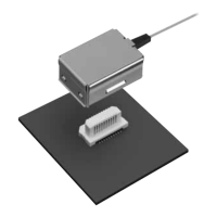
Active Optical Connector V Series
–3–
ACCTB69E 201602-T
3. Materials specifications
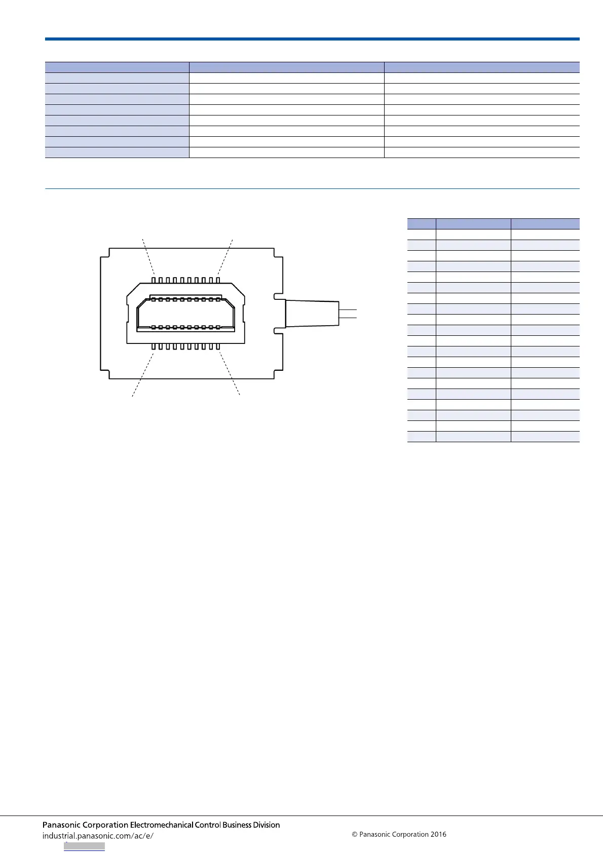
TERMINAL LAYOUT
Component name Materials Specifications and Remarks
Shell Copper alloy Nickel plating
Bushing Elastomer Black
Optical fiber Silica, UV-cured resin Cross section: 0.4 × 0.6 mm, 2 cores
Connector LCP resin, copper alloy Terminal (Au-plating on Ni-base)
Photoelectric conversion PC board Glass-fibered epoxy, epoxy resin, etc. —
IC CMOS —
LD GaAs —
Photo diode GaAs —
11 12 13 14 15 16 17 18 19 20
Optical fiber side
1 2 3 4 5 6 7 8 9 10
Receptacle terminal No.
Terminal layout diagram
(Viewed from the top, receptacle as transparent)
Receptacle
No. Name Wiring
1 Open No connection
2 GND —
3 Differential output − Differential output
4 Differential output + Differential output
5 GND —
6 Open No connection
7 Open No connection
8 Power Supply 3.3V DC
9 Power Supply 3.3V DC
10 GND —
11 Open No connection
12 GND —
13 Differential input − Differential input
14 Differential input + Differential input
15 GND —
16 GND —
17 Power Supply 3.3V DC
18 Power Supply 3.3V DC
19 Power Supply 3.3V DC
20 GND —
Downloaded from Arrow.com.Downloaded from Arrow.com.Downloaded from Arrow.com.