14
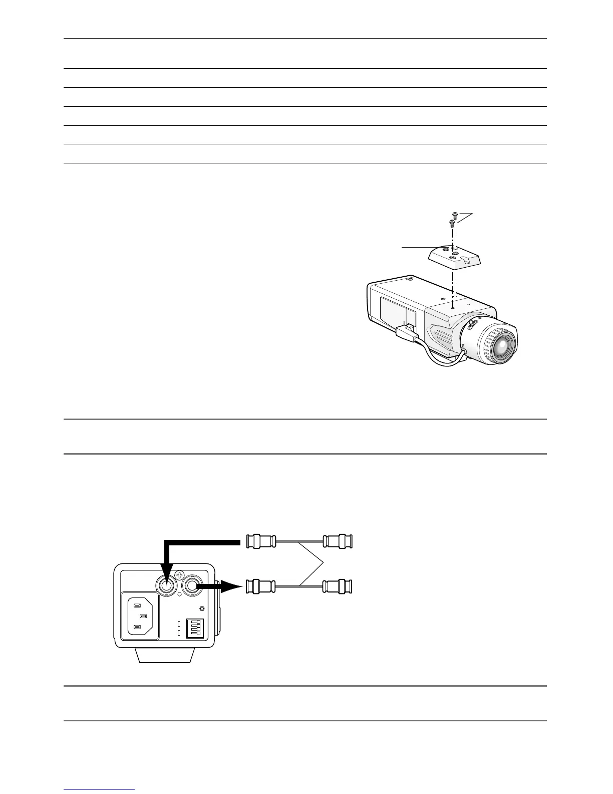
v Establish the connection of a coaxial cable (locally procured).
Important:
• Be sure to turn off the power of each device before connection.
Connect a coaxial cable (locally procured) to the video output connector. If the synchroniz-
ing signal input is provided from an external device, connect another coaxial cable to the
external synchronization input connector.
Important:
• Be sure to secure the coaxial cable connectors.
Tripod socket hole:
1/4-20 UNC
Screws
Tripod socket
GEN-LOCK VIDEO OUT
POWER
ALARM
DAY/
NIGHT
GND
GND
IN
OUT
From external synchronization source
(VBS/VS)
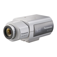
(This illustration represents WV-CL930.)
To video input (CAMERA IN)
Coaxial cables (locally procured)
120V ~ 60Hz
• When the tripod socket is mounted on
the top of the camera, be sure to use the
screws that were removed from the tri-
pod socket. Use of longer or shorter
screws may cause drop or damage.
(Recommended tightening torque: 0.39
N·m {0.29 lbf·ft})
Applicable
mounting base
Installation
position
Recommend-
ed screw
Screw
quantity
Minimum pull-out
strength (per 1 screw)
WV-7011On ceiling M6 4 pieces 196 N {44 lbf}
WV-7010 M8 3 pieces 196 N {44 lbf}
WV-7012 M6 3 pieces 196 N {44 lbf}
WV-831On wall M8 4 pieces 921 N {207 lbf}
WV-7013 M6 3 pieces 2.25 kN {505 lbf}
For some applicable mounting bases, "A" is attached to the model number. The mounting con-
ditions are the same even for the A-attached models.
 Loading...