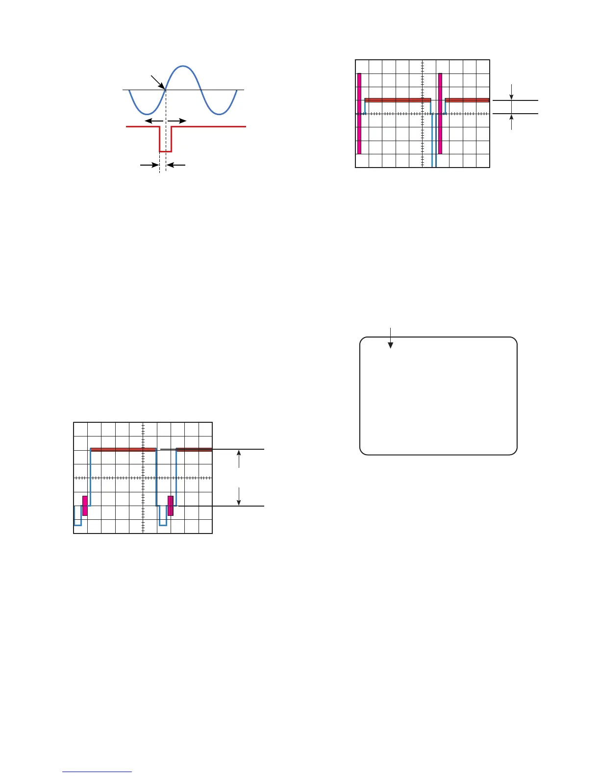
Fig. 4-1-3
8 Press the ENTER key for the next adjustment.
8 Adjust data with the ARROW keys so that the decay point
of V-sync signal gains 2H ± 4H from the zero-cross point
of the AC Power Line Input Waveforms as shown in Fig.
4-1-3.
8 Press the ENTER key for the next adjustment.
(5) High Clip Level Adjustment
Test Point: Video Output Connector
8 Aim the Camera at the Logarithmic Grayscale Chart.
8 Connect the terminated Oscilloscope with 75Ω to the
Video Output Connector.
8 Trigger the Oscilloscope at H-rate.
8 Adjust data with the ARROW keys so that the High Clip
Level becomes 790 mV ± 30 mV as shown in Fig. 4-1-4.
Fig. 4-1-4
8 Press the ENTER key for the next adjustment.
(6) Pedestal Adjustment
Test Point: Video Output Connector
8 Connect the terminated Oscilloscope with 75Ω to the
Video Output Connector.
8 Adjust data with the ARROW keys so that the Pedestal
level becomes 50 mV ± 5 mV as shown in Fig. 4-1-5.
Fig. 4-1-5
8 Press the ENTER key for the next adjustment.
(7) ALC DC Level Adjustment
Observe: Video Monitor
8 Aim the Camera at the Logarithmic Grayscale Chart.
8 Adjust data with the ARROW keys so that the second data
from left becomes between 00 and 05 on the Video
Monitor as shown in Fig. 4-1-6.
Fig. 4-1-6
8 Press the ENTER key for the next adjustment.
(8) Video Out Gain Adjustment
Test Point: Video Output Connector
8 Aim the Camera at the Logarithmic Grayscale Chart.
8 Connect the terminated Oscilloscope with 75Ω to the
Video Output Connector.
8 Adjust data with the ARROW keys so that the Video
Output signal level becomes 700 mV ± 50 mV as shown in
Fig. 4-1-7.
Second data becomes between 00 and 05.
 Loading...