ADJUSTMENT PROCEDURE
1. Test Equipments Required
8
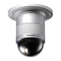
The following Test Equipments are required for
adjustment of the Combination Camera WV-
CS850B/CS854BE.
8
Oscilloscope
8
Frequency Counter
8
Digital Voltmeter
8
Vectorscope
8
Underscanned Colour Video Monitor
8
12 V DC Power Supply Unit
8
Lux Meter
8
Lighting (275 footcandles (2 750 lx), Colour Temperature
3 200 ˚K)
8
Personal Computer (IBM PC/AT type or equivalent)
8
Standard Straight RS-232C Cable
8
White Chart or White Paper
8
Radiation Chart
8
Colour Temperature Conversion Filters as shown in Table
1-1.
Table 1-1
8
Logarithmic Gray Scale Chart (Part No.: YWV2310RB99).
8
Colour Chip Chart (Part No.: YWV2100RB98).
8
System Controller such as WV-CU151 or WV-CU161.
8
Electric Variable Resistor (E.V.R.) kit (Part No.:
YWV0EA1174AN) as shown in Fig. 1-1.
Fig. 1-1
8
Extension Cable for the Power Board and the Base Unit
(Part No.:V0EA1266AN) as shown in Fig. 1-2.
Fig. 1-2
8
Extension Board Ass'y A - D(Part No.: V0EA1265AN).
Extension Cable A for CN201 of the Main Board and
the Lens as shown in Fig. 1-3.
Fig. 1-3
Extension Cable B for CN4 of the Main Board and CN1
of the Servo Board as shown in Fig. 1-4.
Fig. 1-4
Extension Cable C for CN5 of the Servo Board and the
Pan Motor as shown in Fig. 1-5.
Fig. 1-5
Extension Cable C for CN2 of the Servo Board and the
Tilt Motor as shown in Fig. 1-6.
Fig. 1-6
Extension Cable D for CN1 and CN2 of the
Communication Board and the Base Unit as shown in
Fig. 1-7.
Fig. 1-7
8
CCD Mounting Adjustment Jig (Part No. : V0MA1120AN)
as shown in Fig. 1-8.
Fig. 1-8
Part No. Description
 Loading...

