Do you have a question about the P&B MPR3E5 and is the answer not in the manual?
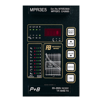
Describes the location and grouping of operational and adjustment elements.
Details how to navigate display modes and access setting procedures.
Details the step-by-step process for configuring various relay parameters.
Defines the time the relay takes to trip at 6 times FLC based on the cold characteristic.
Explains how the speed switch reduces operation times during motor stalls.
Describes setting the relay to the machine's normal running full load current.
Specifies setting the CT primary rating equal to the line CT rating in primary amps.
Sets the available thermal capacity for a motor running at FLC in the hot condition.
Activates an alarm relay when thermal capacity reaches the pre-alarm level.
Specifies the pickup level for Earth Fault Current as a percentage of rating.
Determines the trip time after the earth fault current exceeds the pickup value.
Sets the pickup level for unbalance current as a percentage of FLC.
Enables quicker trip times for high fault currents, recommended for circuit breakers.
Determines the trip time for measured current exceeding the high set pickup.
Allows quicker trip times for fault currents or overloads of medium magnitude.
Sets the trip time after measured current exceeds the low set pickup value.