14/1/98 Page 24 Issue H
8. Relay case
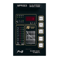
The MPR 3E5 is delivered in an individual case for flush mounting.
8.1 Individual case
The MPR 3E5 is supplied in a UK manufactured industry standard drawout case suitable for flush
mounting. For case dimension and cut-out, refer to Technical Data.
8.2 Rack mounting
MPR 3E5 relays may be supplied mounted in 19" racks if specified by the user.
8.3 Terminal connections
The MPR 3E5 plug in module is supplied in a case which has a very compact plug and socket
connector. The current terminals are equipped with self closing short circuit contacts. Thus the MPR
3E5 module can be unplugged even with current flowing without endangering personnel.
9. Commissioning And Testing The MPR3E5.
9.1. Commissioning.
Auxiliary Power Supply
The relay requires an auxiliary power supply connected to terminals 1 & 2
Two auxiliary power supply versions are available:
Vaux = 24V in a range from 16V to 60V AC 50/60Hz
or in a range from 16V to 80V DC
Vaux = 110V in a range from 50V to 265V AC 50/60Hz
or in a range from 70V to 265V DC
When the stall input is used, the above auxiliary supply or an alternative supply, within the same
range should be connected to terminals 19, & 20 via a speed switch.
Requirements for the main Current Transformers
In order to ensure the correct operation of the MPR 3E5 range of relays, Protection class CT's to
BS3938/BS7626(IEC185) must be utilised. Measuring CT's are generally NOT a suitable alternative.
CT's should be chosen such that saturation, or loss of accuracy does not occur within the settings and
operation ranges of the relays. In the absence of known settings the following may be regarded as an
approximate guide.
For the Line CT’s
For 1A secondary
CT class 5P10 or 10P10 2.5VA (Allowing for up to 1.5Ω of secondary lead resistance)