14/1/98 Page 19 Issue H
203
DIP switch No1 on the 8 way internal switch-group selects the CT Secondary current of the Earth
Fault input for a core balance application only i.e. when the matrix Ennn is set at E129 and above.
See Section 4.13.
For example, if the core balance CT Secondary is 1A and is used with a 5A Earth Fault rated relay,
then the DIP Switch No 1 would be left at its normal setting of "OFF".
Example 2-Residual Connection:
To configure the relay for 3 line CT’s, residually connected for the earth fault input, the core balance
CT option is NOT selected i.e. numerical value 128 set to “N” i.e. value zero and a primary rating
cannot be entered i.e. numbers between 1 and 128 are not possible. The position of DIP Switch No 1
is not relevant in this case.
7.4.5 Trip/ Reset Matrix, Rnnn
This setting, range 000 to 255, sets which Trips are to be self-reset; those not selected have to be
manually reset.
Example
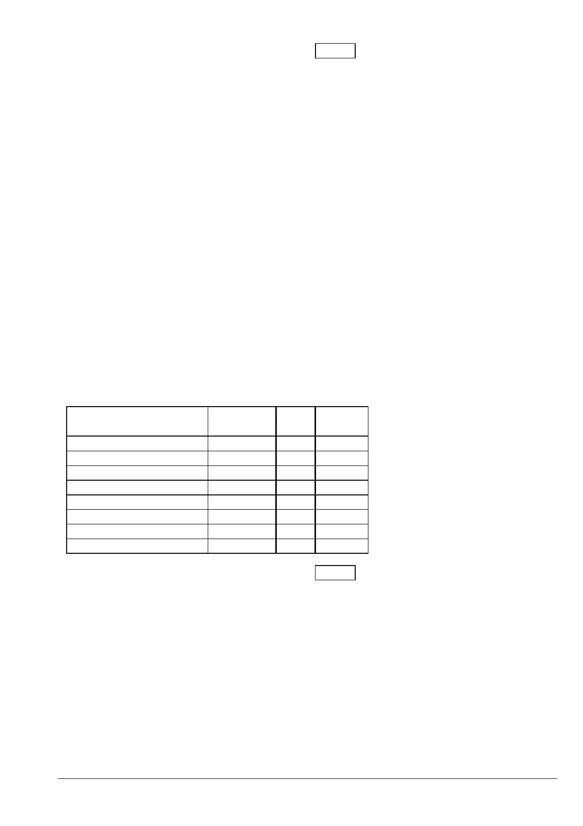
To configure the relay such that only Earth Fault Trips, Low Set Trips and Thermal Overload Trips
are self-reset, then the following value would be set: 161
Action Numerical
Value
Set
Y/N
Value
Earth Fault 128 Y 128
High Set 64
Low Set 32 Y 32
NPS 16
Number of Starts 8
Undercurrent 4
Phase Rotation 2
Thermal Overload 1 Y 1
161
All other Trips would need to be manually reset although a Serial Link Reset always resets the relay
regardless of whether set to manual or self-reset.
7.4.6 Thermal O/L Matrix, Cnnn
This setting, range 001 to 255, Enables/Disables the Hot Restart and selects the Cooling Time
Constant.
Example
To configure the relay such that a Hot Restart is allowed and the Cooling Time Constant is 20 times
the Heating Constant, then the value set would be: 168