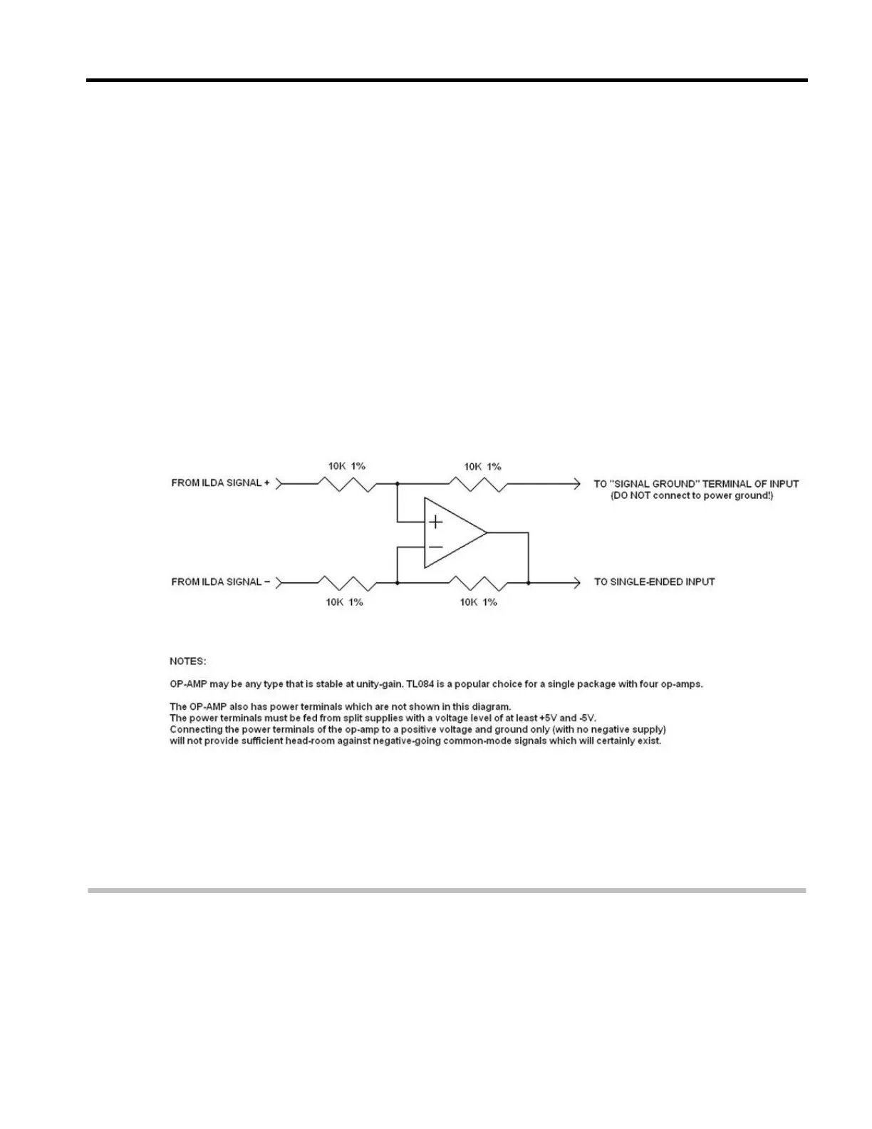
One easy way to do this is with a difference amplifier, as shown in
Figure 5, below. A single op-amp along with four resistors can be
used to receive the differential signal from the X, Y, R, G, or B signal,
and generate a “single ended” signal which is then connected to the
scanner amplifier or laser diode driver. Note that this circuit is drawn
and implemented in such a way that it has two inputs and also two
outputs. One of the outputs is the “single-ended” signal that drives the
component, but the other output is a “ground reference”. This needs to
be connected to the “Signal ground” input terminal of the scanner
amplifier or laser diode driver. The connection is made this way in
lieu of connecting this to any other ground, so that “Ground Bounce”
can be detected and rejected by this circuit. Also note that this
diagram does not show the pin numbers of the op-amp, and also omits
the op-amp power supply connections for clarity. The op-amp must
receive power from a power supply that is capable of feeding it a
minimum of +5V and –5V.
Figure 5, Difference Amplifier
TTL Versus Analog Color Modulation
(Avoiding Fires)
The ISP standard requires the color signals to respond in an analog
fashion, such that 0V does not produce any light from the projector,
2.5V produces around half the nominal laser power, and 5V produces
the full laser power. The ISP standard also assumes that if the laser